Part 1
요약·해설
K64F sensor/power 구조와 KW40Z BLE·802.15.4 controller를 분리해 설명하고, OpenSDA switch 전환·Bluetooth HCI modem·heart-rate sample·RTT console까지 연결합니다.
K64x · Cortex-M4 · 120 MHz
KW40Z · BLE · 802.15.4
OLED · Touch · Haptic · Sensors
Part 2
접을 수 있는 영어 원문 전체
영어 원문 전체 펼치기
8EF15C8D8E5DFBDF60159616934BFDF4CE041C83593CD46749F01FB28BE6E0E3
.. _hexiwear:

Hexiwear
########

Overview
********

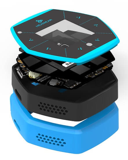
Hexiwear is powered by a Kinetis K64 microcontroller based on the ARM Cortex-M4
core. Another Kinetis wireless MCU, the KW40Z, provides Bluetooth Low Energy
connectivity. Hexiwear also integrates a wide variety of sensors, as well as a
user interface consisting of a 1.1" 96px x 96px full color OLED display and six
capacitive buttons with haptic feedback.

- Eye-catching Smart Watch form factor with powerful, low power Kinetis K6x MCU
  and 6 on-board sensors.
- Designed for wearable applications with the onboard rechargeable battery,
  OLED screen and onboard sensors such as optical heart rate, accelerometer,
  magnetometer and gyroscope.
- Designed for IoT end node applications with the onboard sensor's such as
  temperature, pressure, humidity and ambient light.
- Flexibility to let you add the sensors of your choice nearly 200 additional
  sensors through click boards.

.. image:: ../../../../../../../boards/nxp/hexiwear/doc/hexiwear_k64.jpg
   :align: center
   :alt: Hexiwear

Hardware
********

- Main MCU: NXP Kinetis K64x (ARM Cortex-M4, 120 MHz, 1M Flash, 256K SRAM)
- Wireless MCU: NXP Kinetis KW4x (ARM Cortex-M0+, Bluetooth Low Energy &
  802.15.4 radio)
- 6-axis combo Accelerometer and Magnetometer NXP FXOS8700
- 3-Axis Gyroscope: NXP FXAS21002
- Absolute Pressure sensor NXP MPL3115
- Li-Ion/Li-Po Battery Charger NXP MC34671
- Optical heart rate sensor Maxim MAX30101
- Ambient Light sensor, Humidity and Temperature sensor
- 1.1" full color OLED display
- Haptic feedback engine
- 190 mAh 2C Li-Po battery
- Capacitive touch interface
- RGB LED

For more information about the K64F SoC and Hexiwear board:

- `K64F Website`_
- `K64F Datasheet`_
- `K64F Reference Manual`_
- `Hexiwear Website`_
- `Hexiwear Fact Sheet`_
- `Hexiwear Schematics`_

Supported Features
==================

The hexiwear/mk64f12 board variant supports the following hardware features:

+-----------+------------+-------------------------------------+
| Interface | Controller | Driver/Component                    |
+===========+============+=====================================+
| NVIC      | on-chip    | nested vector interrupt controller  |
+-----------+------------+-------------------------------------+
| SYSTICK   | on-chip    | systick                             |
+-----------+------------+-------------------------------------+
| PINMUX    | on-chip    | pinmux                              |
+-----------+------------+-------------------------------------+
| GPIO      | on-chip    | gpio                                |
+-----------+------------+-------------------------------------+
| I2C       | on-chip    | i2c                                 |
+-----------+------------+-------------------------------------+
| WATCHDOG  | on-chip    | watchdog                            |
+-----------+------------+-------------------------------------+
| ADC       | on-chip    | adc                                 |
+-----------+------------+-------------------------------------+
| PWM       | on-chip    | pwm                                 |
+-----------+------------+-------------------------------------+
| UART      | on-chip    | serial port-polling;                |
|           |            | serial port-interrupt               |
+-----------+------------+-------------------------------------+
| FLASH     | on-chip    | soc flash                           |
+-----------+------------+-------------------------------------+
| SENSOR    | off-chip   | fxos8700 polling;                   |
|           |            | fxos8700 trigger;                   |
|           |            | fxas21002 polling;                  |
|           |            | fxas21002 trigger;                  |
|           |            | max30101 polling                    |
+-----------+------------+-------------------------------------+
| RNGA      | on-chip    | entropy;                            |
|           |            | random                              |
+-----------+------------+-------------------------------------+

The default configuration can be found in the defconfig file:

	:zephyr_file:`boards/nxp/hexiwear/hexiwear_mk64f12_defconfig`

Other hardware features are not currently supported by the port.

Connections and IOs
===================

The K64F SoC has five pairs of pinmux/gpio controllers.

+-------+-----------------+---------------------------+
| Name  | Function        | Usage                     |
+=======+=================+===========================+
| PTA29 | GPIO            | LDO_EN                    |
+-------+-----------------+---------------------------+
| PTB0  | I2C0_SCL        | I2C / MAX30101            |
+-------+-----------------+---------------------------+
| PTB1  | I2C0_SDA        | I2C / MAX30101            |
+-------+-----------------+---------------------------+
| PTB12 | GPIO            | 3V3B EN                   |
+-------+-----------------+---------------------------+
| PTB16 | UART0_RX        | UART Console              |
+-------+-----------------+---------------------------+
| PTB17 | UART0_TX        | UART Console              |
+-------+-----------------+---------------------------+
| PTC8  | GPIO / PWM      | Red LED                   |
+-------+-----------------+---------------------------+
| PTC9  | GPIO / PWM      | Green LED                 |
+-------+-----------------+---------------------------+
| PTC10 | I2C1_SCL        | I2C / FXOS8700 / FXAS21002|
+-------+-----------------+---------------------------+
| PTC11 | I2C1_SDA        | I2C / FXOS8700 / FXAS21002|
+-------+-----------------+---------------------------+
| PTC14 | GPIO            | Battery sense enable      |
+-------+-----------------+---------------------------+
| PTC18 | GPIO            | FXAS21002 INT2            |
+-------+-----------------+---------------------------+
| PTD0  | GPIO / PWM      | Blue LED                  |
+-------+-----------------+---------------------------+
| PTD13 | GPIO            | FXOS8700 INT2             |
+-------+-----------------+---------------------------+
| PTE24 | UART4_RX        | UART BT HCI               |
+-------+-----------------+---------------------------+
| PTE25 | UART4_TX        | UART BT HCI               |
+-------+-----------------+---------------------------+

.. note::

   To enable battery sensing, you will need to enable the ``en_bat_sens``
   regulator in Devicetree. Similarly, to enable devices connected to the 1V8
   or 3V3 power rails (sensors), you will need to enable the ``en_ldo``
   and ``en_3v3b`` regulators in Devicetree.

System Clock
============

The K64F SoC is configured to use the 12 MHz external oscillator on the board
with the on-chip PLL to generate a 120 MHz system clock.

Serial Port
===========

The K64F SoC has six UARTs. One is configured for the console, another for BT
HCI, and the remaining are not used.

Programming and Debugging
*************************

Build and flash applications as usual (see :ref:`build_an_application` and
:ref:`application_run` for more details).

Configuring a Debug Probe
=========================

A debug probe is used for both flashing and debugging the board. This board is
configured by default to use the :ref:`opensda-daplink-onboard-debug-probe`,
but because Segger RTT is required for a console on KW40Z, we recommend that
you reconfigure the board for the :ref:`opensda-jlink-onboard-debug-probe`.

.. note::
   OpenSDA is shared between the K64 and the KW40Z via switches, therefore only
   one SoC can be flashed, debugged, or have an open console at a time.

Option 1: :ref:`opensda-jlink-onboard-debug-probe` (Recommended)
----------------------------------------------------------------

Install the :ref:`jlink-debug-host-tools` and make sure they are in your search
path.

Follow the instructions in :ref:`opensda-jlink-onboard-debug-probe` to program
the `OpenSDA J-Link Generic Firmware for V2.1 Bootloader`_. Check that switches
SW1 and SW2 are **on**, and SW3 and SW4 are **off**  to ensure K64F SWD signals
are connected to the OpenSDA microcontroller.

Option 2: :ref:`opensda-daplink-onboard-debug-probe`
----------------------------------------------------

Install the :ref:`pyocd-debug-host-tools` and make sure they are in your search
path.

Follow the instructions in :ref:`opensda-daplink-onboard-debug-probe` to
program the `OpenSDA DAPLink Hexiwear Firmware`_. Check that switches SW1 and
SW2 are **on**, and SW3 and SW4 are **off**  to ensure K64F SWD signals are
connected to the OpenSDA microcontroller.

Add the arguments ``-DBOARD_FLASH_RUNNER=pyocd`` and
``-DBOARD_DEBUG_RUNNER=pyocd`` when you invoke ``west build`` to override the
default runner from J-Link to pyOCD:

.. zephyr-app-commands::
   :zephyr-app: samples/hello_world
   :board: hexiwear/mk64f12
   :gen-args: -DBOARD_FLASH_RUNNER=pyocd -DBOARD_DEBUG_RUNNER=pyocd
   :goals: build

Configuring a Console
=====================

Regardless of your choice in debug probe, we will use the OpenSDA
microcontroller as a usb-to-serial adapter for the serial console.

Connect a USB cable from your PC to CN1.

Use the following settings with your serial terminal of choice (minicom, putty,
etc.):

- Speed: 115200
- Data: 8 bits
- Parity: None
- Stop bits: 1

Flashing
========

Here is an example for the :ref:`hello_world` application.

.. zephyr-app-commands::
   :zephyr-app: samples/hello_world
   :board: hexiwear/mk64f12
   :goals: flash

Open a serial terminal, reset the board (press the T4 button), and you should
see the following message in the terminal:

.. code-block:: console

   ***** Booting Zephyr OS v1.14.0-rc1 *****
   Hello World! hexiwear

Debugging
=========

Here is an example for the :ref:`hello_world` application.

.. zephyr-app-commands::
   :zephyr-app: samples/hello_world
   :board: hexiwear/mk64f12
   :goals: debug

Open a serial terminal, step through the application in your debugger, and you
should see the following message in the terminal:

.. code-block:: console

   ***** Booting Zephyr OS v1.14.0-rc1 *****
   Hello World! hexiwear

Using Bluetooth
***************

Configure the KW40Z as a Bluetooth controller
=============================================

The K64 can support Zephyr Bluetooth host applications when you configure the
KW40Z as a Bluetooth controller.

#. Download and install the `KW40Z Connectivity Software`_. This package
   contains Bluetooth controller application for the KW40Z.
#. Flash the file ``tools/binaries/BLE_HCI_Modem.bin`` to the KW40Z.

Now you can build and run the sample Zephyr Bluetooth host applications on the
K64. You do not need to repeat this step each time you flash a new Bluetooth
host application to the K64.

Peripheral Heart Rate Sensor
============================

Navigate to the Zephyr ``samples/bluetooth/peripheral_hr`` sample
application, then build and flash it to the Hexiwear K64. Make sure
the OpenSDA switches on the docking station are configured for the
K64.

.. zephyr-app-commands::
   :zephyr-app: samples/bluetooth/peripheral_hr
   :board: hexiwear/mk64f12
   :goals: build flash

Reset the KW40Z and the K64 using the push buttons on the docking station.

Install the Kinetis BLE Toolbox on your smartphone:

- `Kinetis BLE Toolbox for iOS`_
- `Kinetis BLE Toolbox for Android`_

Open the app, tap the **Heart Rate** feature, and you should see a **Zephyr
Heartrate Sensor** device. Tap the **Zephyr Heartrate Sensor** device and you
will then see a plot of the heart rate data that updates once per second.


.. _Hexiwear Website:
   https://www.mikroe.com/hexiwear

.. _Hexiwear Fact Sheet:
   https://www.nxp.com/docs/en/fact-sheet/HEXIWEAR-FS.pdf

.. _Hexiwear Schematics:
   http://cdn-docs.mikroe.com/images/c/c0/Sch_Hexiwear_MainBoard_v106c.pdf

.. _K64F Website:
   https://www.nxp.com/products/processors-and-microcontrollers/arm-based-processors-and-mcus/kinetis-cortex-m-mcus/k-seriesperformancem4/k6x-ethernet/kinetis-k64-120-mhz-256kb-sram-microcontrollers-mcus-based-on-arm-cortex-m4-core:K64_120

.. _K64F Datasheet:
   https://www.nxp.com/docs/en/data-sheet/K64P144M120SF5.pdf

.. _K64F Reference Manual:
   https://www.nxp.com/docs/en/reference-manual/K64P144M120SF5RM.pdf

.. _OpenSDA J-Link Generic Firmware for V2.1 Bootloader:
   https://www.segger.com/downloads/jlink/OpenSDA_V2_1

.. _OpenSDA DAPLink Hexiwear Firmware:
   https://github.com/MikroElektronika/HEXIWEAR/blob/master/HW/HEXIWEAR_DockingStation/HEXIWEAR_DockingStation_DAPLINK_FW.bin

.. _KW40Z Connectivity Software:
   https://www.nxp.com/webapp/Download?colCode=KW40Z-CONNECTIVITY-SOFTWARE&appType=license&location=null&fpsp=1&WT_TYPE=Protocol%20Stacks&WT_VENDOR=FREESCALE&WT_FILE_FORMAT=exe&WT_ASSET=Downloads&fileExt=.exe&Parent_nodeId=1432854896956716810497&Parent_pageType=product

.. _Kinetis BLE Toolbox for iOS:
   https://itunes.apple.com/us/app/kinetis-ble-toolbox/id1049036961?mt=8

.. _Kinetis BLE Toolbox for Android:
   https://play.google.com/store/apps/details?id=com.freescale.kinetisbletoolbox


Hexiwear KW40Z
##############

Overview
********

The KW40Z is a secondary SoC on the board that provides wireless connectivity
with a multimode BLE and 802.15.4 radio.

For more information about the KW40Z SoC:

- `KW40Z Website`_
- `KW40Z Datasheet`_
- `KW40Z Reference Manual`_

Supported Features
==================

The hexiwear/mkw40z4 board variant supports the following hardware features:

+-----------+------------+-------------------------------------+
| Interface | Controller | Driver/Component                    |
+===========+============+=====================================+
| NVIC      | on-chip    | nested vector interrupt controller  |
+-----------+------------+-------------------------------------+
| SYSTICK   | on-chip    | systick                             |
+-----------+------------+-------------------------------------+
| PINMUX    | on-chip    | pinmux                              |
+-----------+------------+-------------------------------------+
| GPIO      | on-chip    | gpio                                |
+-----------+------------+-------------------------------------+
| ADC       | on-chip    | adc                                 |
+-----------+------------+-------------------------------------+
| UART      | on-chip    | serial port-polling;                |
|           |            | serial port-interrupt               |
+-----------+------------+-------------------------------------+
| RTT       | on-chip    | console                             |
+-----------+------------+-------------------------------------+
| FLASH     | on-chip    | soc flash                           |
+-----------+------------+-------------------------------------+
| TRNG      | on-chip    | entropy                             |
+-----------+------------+-------------------------------------+

The default configuration can be found in the defconfig file:

	:zephyr_file:`boards/nxp/hexiwear/hexiwear_mkw40z4_defconfig`

Other hardware features are not currently supported by the port.

Connections and IOs
===================

The KW40Z SoC has three pairs of pinmux/gpio controllers, but only one is
currently enabled (PORTC/GPIOC) for the hexiwear/mkw40z4 board.

+-------+-----------------+---------------------------+
| Name  | Function        | Usage                     |
+=======+=================+===========================+
| PTB1  | ADC             | ADC0 channel 1            |
+-------+-----------------+---------------------------+
| PTC6  | UART0_RX        | UART BT HCI               |
+-------+-----------------+---------------------------+
| PTC7  | UART0_TX        | UART BT HCI               |
+-------+-----------------+---------------------------+

System Clock
============

The KW40Z SoC is configured to use the 32 MHz external oscillator on the board
with the on-chip FLL to generate a 40 MHz system clock.

Serial Port
===========

The KW40Z SoC has one UART, which is used for BT HCI. There is no UART
available for a console.

Programming and Debugging
*************************

Build and flash applications as usual (see :ref:`build_an_application` and
:ref:`application_run` for more details).

Configuring a Debug Probe
=========================

A debug probe is used for both flashing and debugging the board. This board is
configured by default to use the :ref:`opensda-daplink-onboard-debug-probe`,
but because Segger RTT is required for a console, you must reconfigure the
board for one of the following debug probes instead.

:ref:`opensda-jlink-onboard-debug-probe`
----------------------------------------

Install the :ref:`jlink-debug-host-tools` and make sure they are in your search
path.

Follow the instructions in :ref:`opensda-jlink-onboard-debug-probe` to program
the `OpenSDA J-Link Generic Firmware for V2.1 Bootloader`_. Check that switches
SW1 and SW2 are **off**, and SW3 and SW4 are **on**  to ensure KW40Z SWD signals
are connected to the OpenSDA microcontroller.

Configuring a Console
=====================

The console is available using `Segger RTT`_.

Connect a USB cable from your PC to CN1.

Once you have started a debug session, run telnet:

.. code-block:: console

    $ telnet localhost 19021
    Trying 127.0.0.1...
    Connected to localhost.
    Escape character is '^]'.
    SEGGER J-Link V6.44 - Real time terminal output
    J-Link OpenSDA 2 compiled Feb 28 2017 19:27:57 V1.0, SN=621000000
    Process: JLinkGDBServerCLExe

Flashing
========

Here is an example for the :ref:`hello_world` application.

.. zephyr-app-commands::
   :zephyr-app: samples/hello_world
   :board: hexiwear/mkw40z4
   :goals: flash

The Segger RTT console is only available during a debug session. Use ``attach``
to start one:

.. zephyr-app-commands::
   :zephyr-app: samples/hello_world
   :board: hexiwear/mkw40z4
   :goals: attach

Run telnet as shown earlier, and you should see the following message in the
terminal:

.. code-block:: console

   ***** Booting Zephyr OS v1.14.0-rc1 *****
   Hello World! hexiwear

Debugging
=========

Here is an example for the :ref:`hello_world` application.

.. zephyr-app-commands::
   :zephyr-app: samples/hello_world
   :board: hexiwear/mkw40z4
   :goals: debug

Run telnet as shown earlier, step through the application in your debugger, and
you should see the following message in the terminal:

.. code-block:: console

   ***** Booting Zephyr OS v1.14.0-rc1 *****
   Hello World! hexiwear

.. _KW40Z Website:
   https://www.nxp.com/products/processors-and-microcontrollers/arm-based-processors-and-mcus/kinetis-cortex-m-mcus/w-serieswireless-conn.m0-plus-m4/kinetis-kw40z-2.4-ghz-dual-mode-ble-and-802.15.4-wireless-radio-microcontroller-mcu-based-on-arm-cortex-m0-plus-core:KW40Z

.. _KW40Z Datasheet:
   https://www.nxp.com/docs/en/data-sheet/MKW40Z160.pdf

.. _KW40Z Reference Manual:
   https://www.nxp.com/webapp/Download?colCode=MKW40Z160RM

.. _Segger RTT:
   https://www.segger.com/products/debug-probes/j-link/technology/about-real-time-transfer/

.. _OpenSDA J-Link Generic Firmware for V2.1 Bootloader:
   https://www.segger.com/downloads/jlink/OpenSDA_V2_1
Part 3
한국어 전문 번역
개요
Hexiwear의 main processor는 Arm Cortex-M4 기반 Kinetis K64 microcontroller이며, 별도의 Kinetis KW40Z wireless MCU가 Bluetooth Low Energy 연결을 제공합니다. 1.1-inch 96×96 full-color OLED display와 haptic feedback을 지원하는 capacitive button 6개, 다양한 sensor를 통합합니다.
- low-power Kinetis K6x MCU와 on-board sensor 6개를 갖춘 smart-watch form factor
- rechargeable battery, OLED, optical heart-rate, accelerometer, magnetometer, gyroscope를 사용한 wearable application
- temperature, pressure, humidity, ambient-light sensor를 사용한 IoT end node
- click board를 통해 약 200개 additional sensor 확장
하드웨어
- Main MCU: NXP Kinetis K64x, Cortex-M4, 120 MHz, 1 MB flash, 256 KB SRAM
- Wireless MCU: NXP Kinetis KW4x, Cortex-M0+, BLE와 802.15.4 radio
- 6-axis
FXOS8700accelerometer/magnetometer - 3-axis
FXAS21002gyroscope MPL3115absolute-pressure sensorMC34671Li-Ion/Li-Po battery chargerMAX30101optical heart-rate sensor- ambient-light, humidity, temperature sensor
- 1.1-inch full-color OLED, haptic feedback engine, 190 mAh 2C Li-Po battery, capacitive touch, RGB LED
K64F Application Processor
지원 기능
| 인터페이스 | 컨트롤러 | 드라이버/컴포넌트 |
|---|---|---|
NVIC | on-chip | nested vector interrupt controller |
SYSTICK | on-chip | systick |
PINMUX | on-chip | pinmux |
GPIO | on-chip | gpio |
I2C | on-chip | i2c |
WATCHDOG | on-chip | watchdog |
ADC | on-chip | adc |
PWM | on-chip | pwm |
UART | on-chip | serial port-polling; serial port-interrupt |
FLASH | on-chip | soc flash |
SENSOR | off-chip | fxos8700 polling; fxos8700 trigger; fxas21002 polling; fxas21002 trigger; max30101 polling |
RNGA | on-chip | entropy; random |
hexiwear/mk64f12 기본 구성은 boards/nxp/hexiwear/hexiwear_mk64f12_defconfig에 있습니다.
연결과 입출력
K64F SoC에는 pinmux/GPIO controller 쌍이 5개 있습니다.
| 이름 | 기능 | 용도 |
|---|---|---|
PTA29 | GPIO | LDO_EN |
PTB0 | I2C0_SCL | I2C / MAX30101 |
PTB1 | I2C0_SDA | I2C / MAX30101 |
PTB12 | GPIO | 3V3B EN |
PTB16 | UART0_RX | UART Console |
PTB17 | UART0_TX | UART Console |
PTC8 | GPIO / PWM | Red LED |
PTC9 | GPIO / PWM | Green LED |
PTC10 | I2C1_SCL | I2C / FXOS8700 / FXAS21002 |
PTC11 | I2C1_SDA | I2C / FXOS8700 / FXAS21002 |
PTC14 | GPIO | Battery sense enable |
PTC18 | GPIO | FXAS21002 INT2 |
PTD0 | GPIO / PWM | Blue LED |
PTD13 | GPIO | FXOS8700 INT2 |
PTE24 | UART4_RX | UART BT HCI |
PTE25 | UART4_TX | UART BT HCI |
Clock과 serial
K64F는 12 MHz external oscillator와 on-chip PLL로 120 MHz system clock을 생성합니다. UART 6개 중 하나는 console, 하나는 BT HCI이며 나머지는 사용하지 않습니다.
K64F 프로그래밍과 디버깅
기본 probe는 OpenSDA DAPLink이지만 KW40Z console에 SEGGER RTT가 필요하므로 OpenSDA J-Link 재구성을 권장합니다.
OpenSDA J-Link(권장)
J-Link host tool을 설치하고 OpenSDA J-Link Generic Firmware for V2.1 Bootloader를 program하십시오. K64F SWD signal을 OpenSDA에 연결하도록 SW1과 SW2는 ON, SW3와 SW4는 OFF로 설정합니다.
OpenSDA DAPLink
pyOCD host tool을 설치하고 OpenSDA DAPLink Hexiwear Firmware를 program하십시오. switch 상태는 K64F용과 동일하게 SW1/SW2 ON, SW3/SW4 OFF입니다. 기본 J-Link runner를 pyOCD로 바꾸려면 다음 argument를 사용합니다.
west build -b hexiwear/mk64f12 samples/hello_world -- \
  -DBOARD_FLASH_RUNNER=pyocd -DBOARD_DEBUG_RUNNER=pyocd
K64F console
OpenSDA를 USB-to-serial adapter로 사용합니다. PC에서 CN1으로 연결하고 115200 baud, 8 data bits, parity None, 1 stop bit로 설정하십시오.
K64F flash
west build -b hexiwear/mk64f12 samples/hello_world
west flash
T4 button으로 reset하면 다음 출력이 표시됩니다.
***** Booting Zephyr OS v1.14.0-rc1 *****
Hello World! hexiwear
K64F debug
west build -b hexiwear/mk64f12 samples/hello_world
west debug
debugger에서 단계 실행하면 다음 출력이 표시됩니다.
***** Booting Zephyr OS v1.14.0-rc1 *****
Hello World! hexiwear
Bluetooth 사용
KW40Z를 Bluetooth controller로 구성
K64에서 Zephyr Bluetooth host application을 실행하려면 KW40Z를 Bluetooth controller로 구성합니다.
- Bluetooth controller application이 포함된 KW40Z Connectivity Software를 내려받아 설치합니다.
tools/binaries/BLE_HCI_Modem.bin을 KW40Z에 flash합니다.
이후 K64에서 Zephyr Bluetooth host sample을 build하고 실행할 수 있습니다. K64에 새 host application을 flash할 때마다 이 절차를 반복할 필요는 없습니다.
Peripheral Heart Rate Sensor
samples/bluetooth/peripheral_hr를 Hexiwear K64에 build/flash합니다. docking station의 OpenSDA switch가 K64용으로 설정되어 있어야 합니다.
west build -b hexiwear/mk64f12 samples/bluetooth/peripheral_hr
west flash
docking station의 push button으로 KW40Z와 K64를 reset합니다. smartphone에 Kinetis BLE Toolbox를 설치하고 Heart Rate 기능을 선택하면 Zephyr Heartrate Sensor가 표시됩니다. device를 선택하면 1초마다 갱신되는 heart-rate plot을 볼 수 있습니다.
Hexiwear KW40Z
개요
KW40Z는 multimode BLE 및 802.15.4 radio로 wireless connectivity를 제공하는 secondary SoC입니다.
지원 기능
| 인터페이스 | 컨트롤러 | 드라이버/컴포넌트 |
|---|---|---|
NVIC | on-chip | nested vector interrupt controller |
SYSTICK | on-chip | systick |
PINMUX | on-chip | pinmux |
GPIO | on-chip | gpio |
ADC | on-chip | adc |
UART | on-chip | serial port-polling; serial port-interrupt |
RTT | on-chip | console |
FLASH | on-chip | soc flash |
TRNG | on-chip | entropy |
hexiwear/mkw40z4 기본 구성은 boards/nxp/hexiwear/hexiwear_mkw40z4_defconfig에 있습니다.
연결과 입출력
KW40Z에는 pinmux/GPIO controller 쌍이 3개 있지만 PORTC/GPIOC 하나만 활성화됩니다.
| 이름 | 기능 | 용도 |
|---|---|---|
PTB1 | ADC | ADC0 channel 1 |
PTC6 | UART0_RX | UART BT HCI |
PTC7 | UART0_TX | UART BT HCI |
Clock과 serial
KW40Z는 32 MHz external oscillator와 on-chip FLL로 40 MHz system clock을 생성합니다. UART 하나는 BT HCI에 사용되므로 UART console은 없습니다.
KW40Z 프로그래밍과 디버깅
SEGGER RTT console이 필요하므로 OpenSDA J-Link Generic Firmware for V2.1 Bootloader를 program해야 합니다. KW40Z SWD signal을 연결하도록 SW1/SW2는 OFF, SW3/SW4는 ON으로 설정하십시오.
SEGGER RTT console
PC를 CN1에 연결하고 debug session을 시작한 뒤 telnet을 실행합니다.
telnet localhost 19021
Trying 127.0.0.1...
Connected to localhost.
Escape character is '^]'.
SEGGER J-Link V6.44 - Real time terminal output
J-Link OpenSDA 2 compiled Feb 28 2017 19:27:57 V1.0, SN=621000000
Process: JLinkGDBServerCLExe
KW40Z flash와 attach
west build -b hexiwear/mkw40z4 samples/hello_world
west flash
RTT console은 debug session에서만 사용할 수 있으므로 attach로 session을 시작합니다.
west attachtelnet에서 다음 출력이 표시됩니다.
***** Booting Zephyr OS v1.14.0-rc1 *****
Hello World! hexiwear
KW40Z debug
west build -b hexiwear/mkw40z4 samples/hello_world
west debug
telnet terminal에서 다음 출력이 표시됩니다.
***** Booting Zephyr OS v1.14.0-rc1 *****
Hello World! hexiwear
참고 자료
Source
출처
영어 원문에는 문단, 문서 지시문, 표, 코드, 코드 심벌, 경로를 그대로 보존했습니다.