Part 1
요약·해설
KW41Z의 radio·antenna·power 구성과 28개 기능/핀 항목을 정리하고 DAPLink 또는 J-Link로 hello_world를 flash·debug하는 과정을 설명합니다.
BLE 4.2 · 802.15.4 · Thread
2.4 GHz · PCB F-antenna · SMA
OpenSDA · DAPLink · J-Link
Part 2
접을 수 있는 영어 원문 전체
영어 원문 전체 펼치기
DC3FB301898CCC1D3633B8900B37B7576C08A6C1C5AB4920C2D4DA77DFCC5020
.. _frdm_kw41z:

NXP FRDM-KW41Z
##############

Overview
********

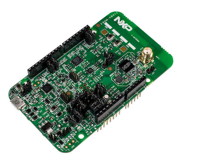
The FRDM-KW41Z is a development kit enabled by the Kinetis |reg| W series
KW41Z/31Z/21Z (KW41Z) family built on ARM |reg| Cortex |reg|-M0+ processor with
integrated 2.4 GHz transceiver supporting Bluetooth |reg| Smart/Bluetooth
|reg| Low Energy
(BLE) v4.2, Generic FSK, IEEE |reg| 802.15.4 and Thread.

The FRDM-KW41Z kit contains two Freedom boards that can be used as a
development board or a shield to connect to a host processor. The FRDM-KW41Z is
form-factor compatible with the Arduino |trade| R3 pin layout for more expansion
options.

The FRDM-KW41Z highly-sensitive, optimized 2.4 GHz radio features a PCB
F-antenna which can be bypassed to test via SMA connection, multiple power
supply options, push/capacitive touch buttons, switches, LEDs and integrated
sensors.

.. image:: ../../../../../../../boards/nxp/frdm_kw41z/doc/frdm_kw41z.jpg
   :align: center
   :alt: FRDM-KW41Z

Hardware
********

- Can be configured as Host or Shield for connection to Host Processor
- Supports all DC-DC configurations (Buck, Boost, Bypass)
- PCB inverted F-type antenna
- SMA RF Connector
- RF regulatory certified
- Serial Flash for OTA firmware upgrades
- On board NXP FXOS8700CQ digital sensor, 3D Accelerometer ( |plusminus| 2g/
  |plusminus| 4g/ |plusminus| 8g) + 3D
  Magnetometer
- OpenSDA and JTAG debug

For more information about the KW41Z SoC and FRDM-KW41Z board:

- `KW41Z Website`_
- `KW41Z Datasheet`_
- `KW41Z Reference Manual`_
- `FRDM-KW41Z Website`_
- `FRDM-KW41Z User Guide`_
- `FRDM-KW41Z Schematics`_

Supported Features
==================

The frdm_kw41z board configuration supports the following hardware features:

+-----------+------------+-------------------------------------+
| Interface | Controller | Driver/Component                    |
+===========+============+=====================================+
| NVIC      | on-chip    | nested vector interrupt controller  |
+-----------+------------+-------------------------------------+
| SYSTICK   | on-chip    | systick                             |
+-----------+------------+-------------------------------------+
| PINMUX    | on-chip    | pinmux                              |
+-----------+------------+-------------------------------------+
| COUNTER   | on-chip    | rtc                                 |
+-----------+------------+-------------------------------------+
| GPIO      | on-chip    | gpio                                |
+-----------+------------+-------------------------------------+
| I2C       | on-chip    | i2c                                 |
+-----------+------------+-------------------------------------+
| SPI       | on-chip    | spi                                 |
+-----------+------------+-------------------------------------+
| ADC       | on-chip    | adc                                 |
+-----------+------------+-------------------------------------+
| UART      | on-chip    | serial port-polling;                |
|           |            | serial port-interrupt               |
+-----------+------------+-------------------------------------+
| FLASH     | on-chip    | soc flash                           |
+-----------+------------+-------------------------------------+
| SENSOR    | off-chip   | fxos8700 polling:                   |
|           |            | fxos8700 trigger                    |
+-----------+------------+-------------------------------------+
| PWM       | on-chip    | tpm                                 |
+-----------+------------+-------------------------------------+
| TRNG      | on-chip    | entropy                             |
+-----------+------------+-------------------------------------+
| FTFA      | on-chip    | flash programming                   |
+-----------+------------+-------------------------------------+

The default configuration can be found in
:zephyr_file:`boards/nxp/frdm_kw41z/frdm_kw41z_defconfig`

Other hardware features are not currently supported by the port.

Connections and IOs
===================

The KW41Z SoC has three pairs of pinmux/gpio controllers, but only two are
currently enabled (PORTA/GPIOA and PORTC/GPIOC) for the FRDM-KW41Z board.

+-------+-------------+---------------------------+
| Name  | Function    | Usage                     |
+=======+=============+===========================+
| PTC1  | GPIO        | Red LED / FXOS8700 INT1   |
+-------+-------------+---------------------------+
| PTA19 | GPIO        | Green LED                 |
+-------+-------------+---------------------------+
| PTA18 | GPIO        | Blue LED                  |
+-------+-------------+---------------------------+
| PTB2  | ADC         | ADC0 channel 3            |
+-------+-------------+---------------------------+
| PTC2  | I2C1_SCL    | I2C / FXOS8700            |
+-------+-------------+---------------------------+
| PTC3  | I2C1_SDA    | I2C / FXOS8700            |
+-------+-------------+---------------------------+
| PTC4  | GPIO        | SW3                       |
+-------+-------------+---------------------------+
| PTC5  | GPIO        | SW4                       |
+-------+-------------+---------------------------+
| PTC6  | LPUART0_RX  | UART Console              |
+-------+-------------+---------------------------+
| PTC7  | LPUART0_TX  | UART Console              |
+-------+-------------+---------------------------+
| PTC16 | SPI0_SCK    | SPI                       |
+-------+-------------+---------------------------+
| PTC17 | SPI0_SOUT   | SPI                       |
+-------+-------------+---------------------------+
| PTC18 | SPI0_SIN    | SPI                       |
+-------+-------------+---------------------------+
| PTC19 | SPI0_PCS0   | SPI                       |
+-------+-------------+---------------------------+

System Clock
============

The KW41Z SoC is configured to use the 32 MHz external oscillator on the board
with the on-chip FLL to generate a 40 MHz system clock.

Serial Port
===========

The KW41Z SoC has one UART, which is used for the console.

Programming and Debugging
*************************

Build and flash applications as usual (see :ref:`build_an_application` and
:ref:`application_run` for more details).

Configuring a Debug Probe
=========================

A debug probe is used for both flashing and debugging the board. This board is
configured by default to use the :ref:`opensda-daplink-onboard-debug-probe`.

Option 1: :ref:`opensda-daplink-onboard-debug-probe` (Recommended)
------------------------------------------------------------------

Install the :ref:`pyocd-debug-host-tools` and make sure they are in your search
path.

Follow the instructions in :ref:`opensda-daplink-onboard-debug-probe` to program
the `OpenSDA DAPLink FRDM-KW41Z Firmware`_.

Option 2: :ref:`opensda-jlink-onboard-debug-probe`
--------------------------------------------------

Install the :ref:`jlink-debug-host-tools` and make sure they are in your search
path.

Follow the instructions in :ref:`opensda-jlink-onboard-debug-probe` to program
the `OpenSDA J-Link FRDM-KW41Z Firmware`_.

Add the arguments ``-DBOARD_FLASH_RUNNER=jlink`` and
``-DBOARD_DEBUG_RUNNER=jlink`` when you invoke ``west build`` to override the
default runner from pyOCD to J-Link:

.. zephyr-app-commands::
   :zephyr-app: samples/hello_world
   :board: frdm_kw41z
   :gen-args: -DBOARD_FLASH_RUNNER=jlink -DBOARD_DEBUG_RUNNER=jlink
   :goals: build

Configuring a Console
=====================

Regardless of your choice in debug probe, we will use the OpenSDA
microcontroller as a usb-to-serial adapter for the serial console.

Connect a USB cable from your PC to J6.

Use the following settings with your serial terminal of choice (minicom, putty,
etc.):

- Speed: 115200
- Data: 8 bits
- Parity: None
- Stop bits: 1

Flashing
========

Here is an example for the :ref:`hello_world` application.

.. zephyr-app-commands::
   :zephyr-app: samples/hello_world
   :board: frdm_kw41z
   :goals: flash

Open a serial terminal, reset the board (press the SW1 button), and you should
see the following message in the terminal:

.. code-block:: console

   ***** Booting Zephyr OS v1.14.0-rc1 *****
   Hello World! frdm_kw41z

Debugging
=========

Here is an example for the :ref:`hello_world` application.

.. zephyr-app-commands::
   :zephyr-app: samples/hello_world
   :board: frdm_kw41z
   :goals: debug

Open a serial terminal, step through the application in your debugger, and you
should see the following message in the terminal:

.. code-block:: console

   ***** Booting Zephyr OS v1.14.0-rc1 *****
   Hello World! frdm_kw41z

.. _FRDM-KW41Z Website:
   https://www.nxp.com/products/processors-and-microcontrollers/arm-based-processors-and-mcus/kinetis-cortex-m-mcus/w-serieswireless-conn.m0-plus-m4/freedom-development-kit-for-kinetis-kw41z-31z-21z-mcus:FRDM-KW41Z

.. _FRDM-KW41Z User Guide:
   https://www.nxp.com/webapp/Download?colCode=FRDMKW41ZUG

.. _FRDM-KW41Z Schematics:
   https://www.nxp.com/webapp/Download?colCode=FRDM-KW41Z-SCH

.. _KW41Z Website:
   https://www.nxp.com/products/wireless/zigbee/kinetis-kw41z-2.4-ghz-dual-mode-bluetooth-low-energy-and-802.15.4-wireless-radio-microcontroller-mcu-based-on-arm-cortex-m0-plus-core:KW41Z

.. _KW41Z Datasheet:
   https://www.nxp.com/docs/en/data-sheet/MKW41Z512.pdf

.. _KW41Z Reference Manual:
   https://www.nxp.com/webapp/Download?colCode=MKW41Z512RM

.. _OpenSDA DAPLink FRDM-KW41Z Firmware:
   https://www.nxp.com/downloads/en/reference-applications/OpenSDAv2.2_DAPLink_frdmkw41z_rev0241.zip

.. _OpenSDA J-Link FRDM-KW41Z Firmware:
   https://www.segger.com/downloads/jlink/OpenSDA_FRDM-KW41Z
Part 3
한국어 전문 번역
개요
FRDM-KW41Z는 Arm Cortex-M0+ processor 기반 Kinetis W series KW41Z/31Z/21Z family를 사용하는 development kit입니다. 통합 2.4 GHz transceiver는 Bluetooth Smart/Bluetooth Low Energy(BLE) v4.2, Generic FSK, IEEE 802.15.4와 Thread를 지원합니다.
kit에는 Freedom board 2개가 들어 있으며 development board 또는 host processor에 연결하는 shield로 사용할 수 있습니다. Arduino R3 pin layout과 form factor가 호환됩니다.
고감도 최적화 2.4 GHz radio에는 PCB inverted-F antenna가 있으며 SMA connection을 이용한 test를 위해 bypass할 수 있습니다. 여러 power option, push/capacitive touch button, switch, LED와 integrated sensor도 제공합니다.
하드웨어
- host processor 연결용 Host 또는 Shield 구성
- 모든 DC-DC 구성 지원: Buck, Boost, Bypass
- PCB inverted F-type antenna와 SMA RF connector
- RF regulatory certification
- OTA firmware upgrade용 serial flash
- on-board NXP
FXOS8700CQdigital sensor: ±2g/±4g/±8g 3D accelerometer와 3D magnetometer - OpenSDA와 JTAG debug
지원 기능
| 인터페이스 | 컨트롤러 | 드라이버/컴포넌트 |
|---|---|---|
NVIC | on-chip | nested vector interrupt controller |
SYSTICK | on-chip | systick |
PINMUX | on-chip | pinmux |
COUNTER | on-chip | rtc |
GPIO | on-chip | gpio |
I2C | on-chip | i2c |
SPI | on-chip | spi |
ADC | on-chip | adc |
UART | on-chip | serial port-polling; serial port-interrupt |
FLASH | on-chip | soc flash |
SENSOR | off-chip | fxos8700 polling; fxos8700 trigger |
PWM | on-chip | tpm |
TRNG | on-chip | entropy |
FTFA | on-chip | flash programming |
기본 구성은 boards/nxp/frdm_kw41z/frdm_kw41z_defconfig에 있습니다. 그 밖의 하드웨어 기능은 현재 이 port에서 지원되지 않습니다.
연결과 입출력
KW41Z SoC에는 pinmux/GPIO controller 쌍이 3개 있지만 FRDM-KW41Z에서는 PORTA/GPIOA와 PORTC/GPIOC 두 쌍만 활성화됩니다.
| 이름 | 기능 | 용도 |
|---|---|---|
PTC1 | GPIO | Red LED / FXOS8700 INT1 |
PTA19 | GPIO | Green LED |
PTA18 | GPIO | Blue LED |
PTB2 | ADC | ADC0 channel 3 |
PTC2 | I2C1_SCL | I2C / FXOS8700 |
PTC3 | I2C1_SDA | I2C / FXOS8700 |
PTC4 | GPIO | SW3 |
PTC5 | GPIO | SW4 |
PTC6 | LPUART0_RX | UART Console |
PTC7 | LPUART0_TX | UART Console |
PTC16 | SPI0_SCK | SPI |
PTC17 | SPI0_SOUT | SPI |
PTC18 | SPI0_SIN | SPI |
PTC19 | SPI0_PCS0 | SPI |
System clock
KW41Z SoC는 보드의 32 MHz external oscillator와 on-chip FLL을 사용해 40 MHz system clock을 생성합니다.
Serial port
KW41Z SoC에는 UART가 하나 있으며 console로 사용됩니다.
프로그래밍과 디버깅
일반적인 Zephyr application과 같은 방식으로 build하고 flash합니다. 기본 probe는 OpenSDA DAPLink on-board debug probe입니다.
선택 1: OpenSDA DAPLink(권장)
pyOCD debug host tool을 설치해 search path에 포함하고, OpenSDA DAPLink 지침에 따라 OpenSDA DAPLink FRDM-KW41Z Firmware를 program하십시오.
선택 2: OpenSDA J-Link
J-Link debug host tool을 설치하고 OpenSDA J-Link 지침에 따라 OpenSDA J-Link FRDM-KW41Z Firmware를 program하십시오. runner를 pyOCD에서 J-Link로 바꾸려면 다음 build argument를 추가합니다.
west build -b frdm_kw41z samples/hello_world -- \
  -DBOARD_FLASH_RUNNER=jlink -DBOARD_DEBUG_RUNNER=jlink
Console 구성
OpenSDA microcontroller를 serial console용 USB-to-serial adapter로 사용합니다. PC에서 J6으로 USB cable을 연결하고 115200 baud, 8 data bits, parity None, 1 stop bit로 설정하십시오.
Flash
west build -b frdm_kw41z samples/hello_world
west flashSW1으로 reset하면 다음 출력이 표시됩니다.
***** Booting Zephyr OS v1.14.0-rc1 *****
Hello World! frdm_kw41z
Debug
west build -b frdm_kw41z samples/hello_world
west debug
debugger에서 application을 단계 실행하면 다음 출력이 표시됩니다.
***** Booting Zephyr OS v1.14.0-rc1 *****
Hello World! frdm_kw41z
참고 자료
Source
출처
영어 원문에는 문단, 문서 지시문, 표, 코드, 코드 심벌, 경로를 그대로 보존했습니다.