Part 1
요약·해설
KE17Z의 sensor와 48 MHz FIRC, UART0 console을 정리하고 J14 외부 J-Link 연결 시 J8/J9 isolation 절차를 설명합니다.
MKE17Z256VLL7 · 72 MHz
256 KB Flash · 48 KB SRAM
LinkServer · External J-Link
Part 2
접을 수 있는 영어 원문 전체
영어 원문 전체 펼치기
A7E1BB6CB10ECD2E5ABD31DA3588FA3ACA019871EB5C0A738F93192B9A716AE1
.. _frdm_ke17z:

NXP FRDM-KE17Z
##############

Overview
********

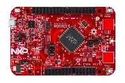
The FRDM-KE17Z is a development board for NXP Kinetis KE1xZ 32-bit
MCU-based platforms. The FRDM-KE17Z contains a robust TSI module
with up to 50 channels which makes this board highly flexible
for touch keys. Offers options for serial
communication, flash programming, and run-control debugging.

.. figure:: ../../../../../../../boards/nxp/frdm_ke17z/doc/frdmke17z.webp
   :align: center
   :alt: FRDM-KE17Z

   FRDM-KE17Z (Credit: NXP)

Hardware
********

- MKE17Z256VLL7 MCU (up to 72 MHz, 256 KB flash memory, 48 KB SRAM,
  and 100 Low profile Quad Flat Package (LQFP))
- 3.3 V or 5 V MCU operation
- 6-axis FXOS8700CQ digital accelerometer
- 3-axis digital angular rate gyroscope
- One RGB LED
- Two user push-buttons
- Thermistor
- Two capacitive touchpads
- Flex I/O pin header

For more information about the KE1xZ SoC and the FRDM-KE17Z board, see
these NXP reference documents:

- `FRDM-KE17Z Website`_
- `FRDM-KE17Z User Guide`_
- `FRDM-KE17Z Reference Manual`_
- `FRDM-KE17Z Datasheet`_

Supported Features
==================

The frdm_ke17z board configuration supports the following hardware
features:

+-----------+------------+-------------------------------------+
| Interface | Controller | Driver/Component                    |
+===========+============+=====================================+
| NVIC      | on-chip    | nested vector interrupt controller  |
+-----------+------------+-------------------------------------+
| SYSTICK   | on-chip    | systick                             |
+-----------+------------+-------------------------------------+
| PINCTRL   | on-chip    | pinctrl                             |
+-----------+------------+-------------------------------------+
| GPIO      | on-chip    | gpio                                |
+-----------+------------+-------------------------------------+
| UART      | on-chip    | uart                                |
+-----------+------------+-------------------------------------+

The default configuration can be found in the defconfig file:
:zephyr_file:`boards/nxp/frdm_ke17z/frdm_ke17z_defconfig`.

Other hardware features are not currently supported by the port.

System Clock
============

The KE17Z SoC is configured to run at 48 MHz using the FIRC.

Serial Port
===========

The KE17Z SoC has three UARTs. UART0 is configured for the console.

Programming and Debugging
*************************

Build and flash applications as usual (see :ref:`build_an_application` and
:ref:`application_run` for more details).

Configuring a Debug Probe
=========================

A debug probe is used for both flashing and debugging the board. This board is
configured by default to use Linkserver.

Early versions of this board have an outdated version of the OpenSDA bootloader
and require an update. Please see the `DAPLink Bootloader Update`_ page for
instructions to update from the CMSIS-DAP bootloader to the DAPLink bootloader.

Option 1: Linkserver
--------------------

Install the :ref:`linkserver-debug-host-tools` and make sure they are in your
search path.  LinkServer works with the default CMSIS-DAP firmware included in
the on-board debugger.

      Linkserver is the default for this board, ``west flash`` and ``west debug`` will
      call the linkserver runner.

.. code-block:: console

   west flash


External JLink: :ref:`jlink-external-debug-probe`
-------------------------------------------------

Install the :ref:`jlink-debug-host-tools` and make sure they are in your search
path.

Attach a J-Link 10-pin connector to J14. Check that jumpers J8 and J9 are
**off** (they are on by default when boards ship from the factory) to ensure
SWD signals are disconnected from the OpenSDA microcontroller.
Use the ``-r jlink`` option with west to use the jlink runner.

.. code-block:: console

   west flash -r jlink

Configuring a Console
=====================

Regardless of your choice in debug probe, we will use the OpenSDA
microcontroller as a usb-to-serial adapter for the serial console.

Connect a USB cable from your PC to J6.

Use the following settings with your serial terminal of choice (minicom, putty,
etc.):

- Speed: 115200
- Data: 8 bits
- Parity: None
- Stop bits: 1

Flashing
========

Here is an example for the :ref:`hello_world` application.

.. zephyr-app-commands::
   :zephyr-app: samples/hello_world
   :board: frdm_ke17z
   :goals: flash

Open a serial terminal, reset the board (press the SW1 button), and you should
see the following message in the terminal:

.. code-block:: console

   *** Booting Zephyr OS build xxxxxxxxxxxx ***
   Hello World! frdm_ke17z/mke17z7

Debugging
=========

Here is an example for the :ref:`hello_world` application.

.. zephyr-app-commands::
   :zephyr-app: samples/hello_world
   :board: frdm_ke17z
   :goals: debug

Open a serial terminal, step through the application in your debugger, and you
should see the following message in the terminal:

.. code-block:: console

   *** Booting Zephyr OS build xxxxxxxxxxxx ***
   Hello World! frdm_ke17z/mke17z7

.. _FRDM-KE17Z Website:
   https://www.nxp.com/design/design-center/development-boards-and-designs/general-purpose-mcus/freedom-development-platform-for-72mhz-ke17z-ke13z-ke12z-mcus:FRDM-KE17Z

.. _FRDM-KE17Z User Guide:
   https://www.nxp.com/docs/en/user-guide/KE17ZHDG.pdf

.. _FRDM-KE17Z Reference Manual:
   https://www.nxp.com/docs/en/reference-manual/KE1xZP100M72SF1RM.pdf

.. _FRDM-KE17Z Datasheet:
   https://www.nxp.com/docs/en/data-sheet/KE1xZP100M72SF1.pdf

.. _DAPLink Bootloader Update:
   https://os.mbed.com/blog/entry/DAPLink-bootloader-update/

.. _OpenSDA DAPLink FRDM-KE17Z Firmware:
   https://www.nxp.com/design/design-center/software/sensor-toolbox/opensda-serial-and-debug-adapter:OPENSDA?tid=vanOpenSDA

.. _linkserver-debug-host-tools:
   https://www.nxp.com/lgfiles/updates/mcuxpresso/LinkServer_1.5.30.exe

.. _OpenSDA J-Link Firmware for FRDM-KE17Z:
   https://www.segger.com/downloads/jlink/OpenSDA_FRDM-KE17Z
Part 3
한국어 전문 번역
개요
FRDM-KE17Z는 NXP Kinetis KE1xZ 32-bit MCU platform용 development board입니다. 최대 50 channel의 TSI module로 touch key를 유연하게 구성할 수 있으며 serial communication, flash programming, run-control debugging을 지원합니다.
하드웨어
MKE17Z256VLL7MCU: 최대 72 MHz, 256 KB flash memory, 48 KB SRAM, 100-pin LQFP- 3.3 V 또는 5 V MCU operation
- 6-axis
FXOS8700CQdigital accelerometer - 3-axis digital angular-rate gyroscope
- RGB LED 1개, user push button 2개
- thermistor와 capacitive touchpad 2개
- Flex I/O pin header
지원 기능
| 인터페이스 | 컨트롤러 | 드라이버/컴포넌트 |
|---|---|---|
NVIC | on-chip | nested vector interrupt controller |
SYSTICK | on-chip | systick |
PINCTRL | on-chip | pinctrl |
GPIO | on-chip | gpio |
UART | on-chip | uart |
기본 구성은 boards/nxp/frdm_ke17z/frdm_ke17z_defconfig에 있습니다. 그 밖의 하드웨어 기능은 현재 이 port에서 지원되지 않습니다.
Clock과 Serial
KE17Z SoC는 FIRC를 사용해 48 MHz로 동작합니다. UART는 3개이며 UART0이 console로 구성됩니다.
프로그래밍과 디버깅
기본 debug probe runner는 LinkServer입니다. 초기 보드의 오래된 OpenSDA bootloader는 DAPLink Bootloader Update 지침에 따라 CMSIS-DAP에서 DAPLink bootloader로 update해야 합니다.
선택 1: LinkServer
LinkServer debug host tool을 설치해 search path에 포함하십시오. on-board debugger의 기본 CMSIS-DAP firmware와 동작하며 west flash와 west debug가 linkserver runner를 호출합니다.
west flashExternal J-Link probe
J-Link debug host tool을 설치하십시오. J-Link 10-pin connector를 J14에 연결하고, OpenSDA microcontroller에서 SWD signal을 분리하도록 출고 시 켜져 있는 jumper J8과 J9를 모두 OFF로 설정하십시오. West에서 -r jlink를 사용합니다.
west flash -r jlinkConsole 구성
OpenSDA를 USB-to-serial adapter로 사용합니다. PC에서 J6으로 USB cable을 연결하고 115200 baud, 8 data bits, parity None, 1 stop bit로 설정하십시오.
Flash
west build -b frdm_ke17z samples/hello_world
west flashSW1으로 reset하면 다음 출력이 표시됩니다.
*** Booting Zephyr OS build xxxxxxxxxxxx ***
Hello World! frdm_ke17z/mke17z7
Debug
west build -b frdm_ke17z samples/hello_world
west debug
debugger에서 단계 실행하면 다음 출력이 표시됩니다.
*** Booting Zephyr OS build xxxxxxxxxxxx ***
Hello World! frdm_ke17z/mke17z7
참고 자료
Source
출처
영어 원문에는 문단, 문서 지시문, 표, 코드, 코드 심벌, 경로를 그대로 보존했습니다.