Part 1
요약·해설
K64F의 21개 지원 interface와 35개 pin, Ethernet·CAN 연결 제약을 정리하고, LinkServer/J-Link runner 설정부터 pyOCD flash 잠금 복구까지 설명합니다.
MK64FN1M0VLL12 · 120 MHz
1 MB Flash · 256 KB RAM
OpenSDAv2 · LinkServer · J-Link
Part 2
접을 수 있는 영어 원문 전체
영어 원문 전체 펼치기
39C5397D7E3BF47D770CB9A7E58E9F5593873FE521D0A42F3FEFF7B630B8154C
.. _frdm_k64f:

NXP FRDM-K64F
##############

Overview
********

The Freedom-K64F is an ultra-low-cost development platform for Kinetis K64,
K63, and K24 MCUs.

- Form-factor compatible with the Arduino R3 pin layout
- Peripherals enable rapid prototyping, including a 6-axis digital
  accelerometer and magnetometer to create full eCompass capabilities, a
  tri-colored LED and 2 user push-buttons for direct interaction, a microSD
  card slot, and connectivity using onboard Ethernet port and headers for use
  with Bluetooth* and 2.4 GHz radio add-on modules
- OpenSDAv2, the NXP open source hardware embedded serial and debug adapter
  running an open source bootloader, offers options for serial communication,
  flash programming, and run-control debugging

.. image:: ../../../../../../../boards/nxp/frdm_k64f/doc/frdm_k64f.jpg
   :align: center
   :alt: FRDM-K64F

Hardware
********

- MK64FN1M0VLL12 MCU (120 MHz, 1 MB flash memory, 256 KB RAM, low-power,
  crystal-less USB, and 100 Low profile Quad Flat Package (LQFP))
- Dual role USB interface with micro-B USB connector
- RGB LED
- FXOS8700CQ accelerometer and magnetometer
- Two user push buttons
- Flexible power supply option - OpenSDAv2 USB, Kinetis K64 USB, and external source
- Easy access to MCU input/output through Arduino* R3 compatible I/O connectors
- Programmable OpenSDAv2 debug circuit supporting the CMSIS-DAP Interface
  software that provides:

  - Mass storage device (MSD) flash programming interface
  - CMSIS-DAP debug interface over a driver-less USB HID connection providing
    run-control debugging and compatibility with IDE tools
  - Virtual serial port interface
  - Open source CMSIS-DAP software project

- Ethernet
- SDHC

For more information about the K64F SoC and FRDM-K64F board:

- `K64F Website`_
- `K64F Datasheet`_
- `K64F Reference Manual`_
- `FRDM-K64F Website`_
- `FRDM-K64F User Guide`_
- `FRDM-K64F Schematics`_

Supported Features
==================

NXP considers the FRDM-K64F as the superset board for the Kinetis K
series of MCUs.  This board is a focus for NXP's Full Platform Support for
Zephyr, to better enable the entire Kinetis K series.  NXP prioritizes enabling
this board with new support for Zephyr features.  The frdm_k64f board
configuration supports the following hardware features:

+-----------+------------+-------------------------------------+
| Interface | Controller | Driver/Component                    |
+===========+============+=====================================+
| NVIC      | on-chip    | nested vector interrupt controller  |
+-----------+------------+-------------------------------------+
| SYSTICK   | on-chip    | systick                             |
+-----------+------------+-------------------------------------+
| PINMUX    | on-chip    | pinmux                              |
+-----------+------------+-------------------------------------+
| GPIO      | on-chip    | gpio                                |
+-----------+------------+-------------------------------------+
| I2C       | on-chip    | i2c                                 |
+-----------+------------+-------------------------------------+
| SPI       | on-chip    | spi                                 |
+-----------+------------+-------------------------------------+
| WATCHDOG  | on-chip    | watchdog                            |
+-----------+------------+-------------------------------------+
| ADC       | on-chip    | adc                                 |
+-----------+------------+-------------------------------------+
| DAC       | on-chip    | dac                                 |
+-----------+------------+-------------------------------------+
| PWM       | on-chip    | pwm                                 |
+-----------+------------+-------------------------------------+
| ETHERNET  | on-chip    | ethernet                            |
+-----------+------------+-------------------------------------+
| UART      | on-chip    | serial port-polling;                |
|           |            | serial port-interrupt               |
+-----------+------------+-------------------------------------+
| FLASH     | on-chip    | soc flash                           |
+-----------+------------+-------------------------------------+
| USB       | on-chip    | USB device                          |
+-----------+------------+-------------------------------------+
| SENSOR    | off-chip   | fxos8700 polling;                   |
|           |            | fxos8700 trigger                    |
+-----------+------------+-------------------------------------+
| CAN       | on-chip    | can                                 |
+-----------+------------+-------------------------------------+
| RTC       | on-chip    | rtc                                 |
+-----------+------------+-------------------------------------+
| DMA       | on-chip    | dma                                 |
+-----------+------------+-------------------------------------+
| RNGA      | on-chip    | entropy;                            |
|           |            | random                              |
+-----------+------------+-------------------------------------+
| FTFE      | on-chip    | flash programming                   |
+-----------+------------+-------------------------------------+
| PIT       | on-chip    | pit                                 |
+-----------+------------+-------------------------------------+

The default configuration can be found in
:zephyr_file:`boards/nxp/frdm_k64f/frdm_k64f_defconfig`

Other hardware features are not currently supported by the port.

Connections and IOs
===================

The K64F SoC has five pairs of pinmux/gpio controllers.

+-------+-----------------+---------------------------+
| Name  | Function        | Usage                     |
+=======+=================+===========================+
| PTB22 | GPIO            | Red LED                   |
+-------+-----------------+---------------------------+
| PTE26 | GPIO            | Green LED                 |
+-------+-----------------+---------------------------+
| PTB21 | GPIO            | Blue LED                  |
+-------+-----------------+---------------------------+
| PTC6  | GPIO            | SW2 / FXOS8700 INT1       |
+-------+-----------------+---------------------------+
| PTC13 | GPIO            | FXOS8700 INT2             |
+-------+-----------------+---------------------------+
| PTA4  | GPIO            | SW3                       |
+-------+-----------------+---------------------------+
| PTB10 | ADC             | ADC1 channel 14           |
+-------+-----------------+---------------------------+
| PTB16 | UART0_RX        | UART Console              |
+-------+-----------------+---------------------------+
| PTB17 | UART0_TX        | UART Console              |
+-------+-----------------+---------------------------+
| PTB18 | CAN0_TX         | CAN TX                    |
+-------+-----------------+---------------------------+
| PTB19 | CAN0_RX         | CAN RX                    |
+-------+-----------------+---------------------------+
| PTC8  | PWM             | PWM_3 channel 4           |
+-------+-----------------+---------------------------+
| PTC9  | PWM             | PWM_3 channel 5           |
+-------+-----------------+---------------------------+
| PTC16 | UART3_RX        | UART BT HCI               |
+-------+-----------------+---------------------------+
| PTC17 | UART3_TX        | UART BT HCI               |
+-------+-----------------+---------------------------+
| PTD0  | SPI0_PCS0       | SPI                       |
+-------+-----------------+---------------------------+
| PTD1  | SPI0_SCK        | SPI                       |
+-------+-----------------+---------------------------+
| PTD2  | SPI0_SOUT       | SPI                       |
+-------+-----------------+---------------------------+
| PTD3  | SPI0_SIN        | SPI                       |
+-------+-----------------+---------------------------+
| PTE24 | I2C0_SCL        | I2C / FXOS8700            |
+-------+-----------------+---------------------------+
| PTE25 | I2C0_SDA        | I2C / FXOS8700            |
+-------+-----------------+---------------------------+
| PTA5  | MII0_RXER       | Ethernet                  |
+-------+-----------------+---------------------------+
| PTA12 | MII0_RXD1       | Ethernet                  |
+-------+-----------------+---------------------------+
| PTA13 | MII0_RXD0       | Ethernet                  |
+-------+-----------------+---------------------------+
| PTA14 | MII0_RXDV       | Ethernet                  |
+-------+-----------------+---------------------------+
| PTA15 | MII0_TXEN       | Ethernet                  |
+-------+-----------------+---------------------------+
| PTA16 | MII0_TXD0       | Ethernet                  |
+-------+-----------------+---------------------------+
| PTA17 | MII0_TXD1       | Ethernet                  |
+-------+-----------------+---------------------------+
| PTA28 | MII0_TXER       | Ethernet                  |
+-------+-----------------+---------------------------+
| PTB0  | MII0_MDIO       | Ethernet                  |
+-------+-----------------+---------------------------+
| PTB1  | MII0_MDC        | Ethernet                  |
+-------+-----------------+---------------------------+
| PTC16 | ENET0_1588_TMR0 | Ethernet                  |
+-------+-----------------+---------------------------+
| PTC17 | ENET0_1588_TMR1 | Ethernet                  |
+-------+-----------------+---------------------------+
| PTC18 | ENET0_1588_TMR2 | Ethernet                  |
+-------+-----------------+---------------------------+
| PTC19 | ENET0_1588_TMR3 | Ethernet                  |
+-------+-----------------+---------------------------+

.. note::
   Do not enable Ethernet and UART BT HCI simultaneously because they conflict
   on PTC16-17.

System Clock
============

The K64F SoC is configured to use the 50 MHz external oscillator on the board
with the on-chip PLL to generate a 120 MHz system clock.

Serial Port
===========

The K64F SoC has six UARTs. One is configured for the console, another for BT
HCI, and the remaining are not used.

USB
===

The K64F SoC has a USB OTG (USBOTG) controller that supports both
device and host functions through its micro USB connector (K64F USB).
Only USB device function is supported in Zephyr at the moment.

CAN
===

The FRDM-K64F board does not come with an onboard CAN transceiver. In order to
use the CAN bus, an external CAN bus transceiver must be connected to ``PTB18``
(``CAN0_TX``) and ``PTB19`` (``CAN0_RX``).

Programming and Debugging
*************************

Build and flash applications as usual (see :ref:`build_an_application` and
:ref:`application_run` for more details).

Configuring a Debug Probe
=========================

A debug probe is used for both flashing and debugging the board. This board is
configured by default to use the :ref:`opensda-daplink-onboard-debug-probe`.

Early versions of this board have an outdated version of the OpenSDA bootloader
and require an update. Please see the `DAPLink Bootloader Update`_ page for
instructions to update from the CMSIS-DAP bootloader to the DAPLink bootloader.

.. tabs::

   .. group-tab:: OpenSDA DAPLink Onboard (Recommended)

	Install the :ref:`linkserver-debug-host-tools` and make sure they are in your
	search path.  LinkServer works with the default CMSIS-DAP firmware included in
	the on-board debugger.

        Linkserver is the default for this board, ``west flash`` and ``west debug`` will
        call the linkserver runner.

	.. code-block:: console

	   west flash

	Alternatively, pyOCD can be used to flash and debug the board by using the
	``-r pyocd`` option with West. pyOCD is installed when you complete the
	:ref:`gs_python_deps` step in the Getting Started Guide. The runners supported
	by NXP are LinkServer and JLink. pyOCD is another potential option, but NXP
	does not test or support the pyOCD runner.


   .. group-tab:: OpenSDA JLink Onboard

        Install the :ref:`jlink-debug-host-tools` and make sure they are in your search
        path.

        The version of J-Link firmware to program to the board depends on the version
        of the DAPLink bootloader. Refer to `OpenSDA Serial and Debug Adapter`_ for
        more details. On this page, change the pull-down menu for "Choose your board to
        start" to FRDM-K64F, and review the section "To update your board with OpenSDA
        applications". Note that Segger does provide an OpenSDA J-Link Board-Specific
        Firmware for this board, however it is not compatible with the DAPLink
        bootloader. After downloading the appropriate J-Link firmware, follow the
        instructions in :ref:`opensda-jlink-onboard-debug-probe` to program to the
        board.

        Add the arguments ``-DBOARD_FLASH_RUNNER=jlink`` and
        ``-DBOARD_DEBUG_RUNNER=jlink`` when you invoke ``west build`` to override the
        default runner to J-Link:

        .. zephyr-app-commands::
           :zephyr-app: samples/hello_world
           :board: frdm_k64f
           :gen-args: -DBOARD_FLASH_RUNNER=jlink -DBOARD_DEBUG_RUNNER=jlink
           :goals: build

Configuring a Console
=====================

Regardless of your choice in debug probe, we will use the OpenSDA
microcontroller as a usb-to-serial adapter for the serial console.

Connect a USB cable from your PC to J26.

Use the following settings with your serial terminal of choice (minicom, putty,
etc.):

- Speed: 115200
- Data: 8 bits
- Parity: None
- Stop bits: 1

Flashing
========

Here is an example for the :ref:`hello_world` application.

.. zephyr-app-commands::
   :zephyr-app: samples/hello_world
   :board: frdm_k64f
   :goals: flash

Open a serial terminal, reset the board (press the SW1 button), and you should
see the following message in the terminal:

.. code-block:: console

   ***** Booting Zephyr OS v1.14.0-rc1 *****
   Hello World! frdm_k64f

Debugging
=========

Here is an example for the :ref:`hello_world` application.

.. zephyr-app-commands::
   :zephyr-app: samples/hello_world
   :board: frdm_k64f
   :goals: debug

Open a serial terminal, step through the application in your debugger, and you
should see the following message in the terminal:

.. code-block:: console

   ***** Booting Zephyr OS v1.14.0-rc1 *****
   Hello World! frdm_k64f

Troubleshooting
===============

If pyocd raises an uncaught ``DAPAccessIntf.TransferFaultError()`` exception
when you try to flash or debug, it's possible that the K64F flash may have been
locked by a corrupt application. You can unlock it with the following sequence
of pyocd commands:

.. code-block:: console

   $ pyocd cmd
   0001915:WARNING:target_kinetis:Forcing halt on connect in order to gain control of device
   Connected to K64F [Halted]: 0240000026334e450028400d5e0e000e4eb1000097969900
   >>> unlock
   0016178:WARNING:target_kinetis:K64F secure state: unlocked successfully
   >>> reinit
   0034584:WARNING:target_kinetis:Forcing halt on connect in order to gain control of device
   >>> load build/zephyr/zephyr.bin
   [====================] 100%
   >>> reset
   Resetting target
   >>> quit

.. _FRDM-K64F Website:
   https://www.nxp.com/support/developer-resources/evaluation-and-development-boards/freedom-development-boards/mcu-boards/freedom-development-platform-for-kinetis-k64-k63-and-k24-mcus:FRDM-K64F

.. _FRDM-K64F User Guide:
   https://www.nxp.com/webapp/Download?colCode=FRDMK64FUG

.. _FRDM-K64F Schematics:
   https://www.nxp.com/webapp/Download?colCode=FRDM-K64F-SCH-E4

.. _K64F Website:
   https://www.nxp.com/products/processors-and-microcontrollers/arm-based-processors-and-mcus/kinetis-cortex-m-mcus/k-seriesperformancem4/k6x-ethernet/kinetis-k64-120-mhz-256kb-sram-microcontrollers-mcus-based-on-arm-cortex-m4-core:K64_120

.. _K64F Datasheet:
   https://www.nxp.com/docs/en/data-sheet/K64P144M120SF5.pdf

.. _K64F Reference Manual:
   https://www.nxp.com/docs/en/reference-manual/K64P144M120SF5RM.pdf

.. _DAPLink Bootloader Update:
   https://os.mbed.com/blog/entry/DAPLink-bootloader-update/

.. _OpenSDA DAPLink FRDM-K64F Firmware:
   https://www.nxp.com/downloads/en/snippets-boot-code-headers-monitors/k20dx_frdmk64f_if_crc_legacy_0x5000.bin

.. _OpenSDA Serial and Debug Adapter:
   https://www.nxp.com/design/microcontrollers-developer-resources/ides-for-kinetis-mcus/opensda-serial-and-debug-adapter:OPENSDA#FRDM-K64F
Part 3
한국어 전문 번역
개요
Freedom-K64F는 Kinetis K64, K63, K24 MCU를 위한 초저가 development platform입니다.
- Arduino R3 pin layout과 호환되는 form factor
- 빠른 prototype 제작용 peripheral: 완전한 eCompass를 구성하는 6-axis digital accelerometer와 magnetometer, tri-color LED, user push button 2개, microSD card slot, on-board Ethernet port, Bluetooth 및 2.4 GHz radio add-on module용 header
- OpenSDAv2: open-source bootloader를 실행하는 NXP open-source hardware embedded serial/debug adapter로 serial communication, flash programming, run-control debugging 선택지를 제공
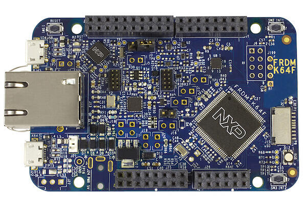
하드웨어
MK64FN1M0VLL12MCU: 120 MHz, 1 MB flash memory, 256 KB RAM, low-power, crystal-less USB, 100-pin LQFP- micro-B USB connector를 사용하는 dual-role USB interface
- RGB LED,
FXOS8700CQaccelerometer/magnetometer, user push button 2개 - 유연한 전원 선택: OpenSDAv2 USB, Kinetis K64 USB, external source
- Arduino R3 compatible I/O connector를 통한 MCU I/O 접근
- CMSIS-DAP interface software를 지원하는 programmable OpenSDAv2 debug circuit
- Ethernet과 SDHC
OpenSDAv2는 MSD flash programming interface, driver가 필요 없는 USB HID 기반 CMSIS-DAP debug interface, run-control debugging과 IDE 호환성, virtual serial port interface, open-source CMSIS-DAP software project를 제공합니다.
지원 기능
NXP는 FRDM-K64F를 Kinetis K series MCU의 superset board로 봅니다. Zephyr Full Platform Support를 통해 Kinetis K series 전체를 더 잘 지원하기 위한 중심 보드이며, NXP는 새로운 Zephyr 기능을 이 보드에 우선 활성화합니다. frdm_k64f board configuration은 다음 기능을 지원합니다.
| 인터페이스 | 컨트롤러 | 드라이버/컴포넌트 |
|---|---|---|
NVIC | on-chip | nested vector interrupt controller |
SYSTICK | on-chip | systick |
PINMUX | on-chip | pinmux |
GPIO | on-chip | gpio |
I2C | on-chip | i2c |
SPI | on-chip | spi |
WATCHDOG | on-chip | watchdog |
ADC | on-chip | adc |
DAC | on-chip | dac |
PWM | on-chip | pwm |
ETHERNET | on-chip | ethernet |
UART | on-chip | serial port-polling; serial port-interrupt |
FLASH | on-chip | soc flash |
USB | on-chip | USB device |
SENSOR | off-chip | fxos8700 polling; fxos8700 trigger |
CAN | on-chip | can |
RTC | on-chip | rtc |
DMA | on-chip | dma |
RNGA | on-chip | entropy; random |
FTFE | on-chip | flash programming |
PIT | on-chip | pit |
기본 구성은 boards/nxp/frdm_k64f/frdm_k64f_defconfig에 있습니다. 그 밖의 하드웨어 기능은 현재 이 port에서 지원되지 않습니다.
연결과 입출력
K64F SoC에는 pinmux/GPIO controller 쌍이 5개 있습니다.
| 이름 | 기능 | 용도 |
|---|---|---|
PTB22 | GPIO | Red LED |
PTE26 | GPIO | Green LED |
PTB21 | GPIO | Blue LED |
PTC6 | GPIO | SW2 / FXOS8700 INT1 |
PTC13 | GPIO | FXOS8700 INT2 |
PTA4 | GPIO | SW3 |
PTB10 | ADC | ADC1 channel 14 |
PTB16 | UART0_RX | UART Console |
PTB17 | UART0_TX | UART Console |
PTB18 | CAN0_TX | CAN TX |
PTB19 | CAN0_RX | CAN RX |
PTC8 | PWM | PWM_3 channel 4 |
PTC9 | PWM | PWM_3 channel 5 |
PTC16 | UART3_RX | UART BT HCI |
PTC17 | UART3_TX | UART BT HCI |
PTD0 | SPI0_PCS0 | SPI |
PTD1 | SPI0_SCK | SPI |
PTD2 | SPI0_SOUT | SPI |
PTD3 | SPI0_SIN | SPI |
PTE24 | I2C0_SCL | I2C / FXOS8700 |
PTE25 | I2C0_SDA | I2C / FXOS8700 |
PTA5 | MII0_RXER | Ethernet |
PTA12 | MII0_RXD1 | Ethernet |
PTA13 | MII0_RXD0 | Ethernet |
PTA14 | MII0_RXDV | Ethernet |
PTA15 | MII0_TXEN | Ethernet |
PTA16 | MII0_TXD0 | Ethernet |
PTA17 | MII0_TXD1 | Ethernet |
PTA28 | MII0_TXER | Ethernet |
PTB0 | MII0_MDIO | Ethernet |
PTB1 | MII0_MDC | Ethernet |
PTC16 | ENET0_1588_TMR0 | Ethernet |
PTC17 | ENET0_1588_TMR1 | Ethernet |
PTC18 | ENET0_1588_TMR2 | Ethernet |
PTC19 | ENET0_1588_TMR3 | Ethernet |
System clock
K64F SoC는 보드의 50 MHz external oscillator와 on-chip PLL을 사용해 120 MHz system clock을 생성하도록 구성됩니다.
Serial port
K64F SoC에는 UART가 6개 있습니다. 하나는 console, 하나는 BT HCI로 구성되고 나머지는 사용하지 않습니다.
USB
K64F SoC의 USB OTG(USBOTG) controller는 K64F USB micro USB connector를 통해 device와 host 기능을 모두 지원합니다. 현재 Zephyr에서는 USB device 기능만 지원됩니다.
CAN
FRDM-K64F에는 on-board CAN transceiver가 없습니다. CAN bus를 사용하려면 external CAN bus transceiver를 PTB18(CAN0_TX)과 PTB19(CAN0_RX)에 연결해야 합니다.
프로그래밍과 디버깅
일반적인 Zephyr application과 같은 방식으로 build하고 flash합니다.
Debug probe 구성
debug probe는 보드의 flash와 debug에 모두 사용됩니다. 이 보드는 기본적으로 OpenSDA DAPLink on-board debug probe를 사용합니다. 초기 version 보드의 오래된 OpenSDA bootloader는 DAPLink Bootloader Update 지침에 따라 CMSIS-DAP에서 DAPLink bootloader로 update해야 합니다.
OpenSDA DAPLink On-board(권장)
LinkServer debug host tool을 설치하고 search path에 포함했는지 확인하십시오. LinkServer는 on-board debugger에 포함된 기본 CMSIS-DAP firmware와 동작합니다. 이 보드의 기본 runner는 LinkServer이므로 west flash와 west debug가 linkserver runner를 호출합니다.
west flash대안으로 West의 -r pyocd option을 사용해 pyOCD로 flash와 debug를 수행할 수 있습니다. pyOCD는 Getting Started Guide의 Python dependency 단계를 완료할 때 설치됩니다. NXP가 지원하는 runner는 LinkServer와 J-Link이며, pyOCD는 가능한 대안이지만 NXP가 test하거나 지원하지 않습니다.
OpenSDA J-Link On-board
J-Link debug host tool을 설치하고 search path에 포함했는지 확인하십시오. 보드에 program할 J-Link firmware version은 DAPLink bootloader version에 따라 달라집니다. OpenSDA Serial and Debug Adapter 페이지에서 board 선택을 FRDM-K64F로 바꾸고 OpenSDA application update 절을 확인하십시오.
SEGGER의 board-specific OpenSDA J-Link firmware는 DAPLink bootloader와 호환되지 않습니다. 적절한 J-Link firmware를 내려받은 다음 OpenSDA J-Link on-board probe 지침에 따라 보드에 program하십시오.
-DBOARD_FLASH_RUNNER=jlink와 -DBOARD_DEBUG_RUNNER=jlink를 추가하면 기본 runner를 J-Link로 바꿀 수 있습니다.
west build -b frdm_k64f samples/hello_world -- \
  -DBOARD_FLASH_RUNNER=jlink -DBOARD_DEBUG_RUNNER=jlink
Console 구성
debug probe 선택과 관계없이 OpenSDA microcontroller를 serial console용 USB-to-serial adapter로 사용합니다. PC에서 J26으로 USB cable을 연결하십시오.
- Speed:
115200 - Data:
8 bits - Parity:
None - Stop bits:
1
Flash
west build -b frdm_k64f samples/hello_world
west flash
serial terminal을 열고 SW1 button을 눌러 보드를 reset하면 다음 메시지가 표시됩니다.
***** Booting Zephyr OS v1.14.0-rc1 *****
Hello World! frdm_k64f
Debug
west build -b frdm_k64f samples/hello_world
west debug
serial terminal을 열고 debugger에서 application을 한 단계씩 실행하면 다음 메시지가 표시됩니다.
***** Booting Zephyr OS v1.14.0-rc1 *****
Hello World! frdm_k64f
문제 해결
flash 또는 debug 시 pyOCD가 처리되지 않은 DAPAccessIntf.TransferFaultError() exception을 발생시키면 손상된 application 때문에 K64F flash가 잠겼을 수 있습니다. 다음 pyOCD command sequence로 잠금을 해제하십시오.
pyocd cmd
0001915:WARNING:target_kinetis:Forcing halt on connect in order to gain control of device
Connected to K64F [Halted]: 0240000026334e450028400d5e0e000e4eb1000097969900
>>> unlock
0016178:WARNING:target_kinetis:K64F secure state: unlocked successfully
>>> reinit
0034584:WARNING:target_kinetis:Forcing halt on connect in order to gain control of device
>>> load build/zephyr/zephyr.bin
[====================] 100%
>>> reset
Resetting target
>>> quit
참고 자료
Source
출처
영어 원문에는 문단, 문서 지시문, 표, 코드, 코드 심벌, 경로를 그대로 보존했습니다.