Part 1
요약·해설
지원 종료 상태를 명확히 표시하고, 내부·외부 I2C와 sensor address, P4 pin 20개, MOSFET, power dependency를 표로 연결하며 외부 J-Link 조건을 설명합니다.
PCA20020
nRF52832 · Cortex-M4F
External J-Link · P9
Part 2
접을 수 있는 영어 원문 전체
영어 원문 전체 펼치기
2DDFA90EFCD6A2B3A61BCE26B378D643D4887A998DF8F77E1CF2C7D2CBE204FE
.. _thingy52_nrf52832:

Thingy:52
#########

.. warning::

   Nordic Semiconductor no longer offers support for this board, so it is not
   recommended for new prototypes.

Overview
********

Zephyr uses the thingy52/nrf52832 (PCA20020) board configuration for building
for the Thingy:52 board. The board has the nRF52832 MCU with ARM Cortex-M4F
processor, a set of environmental sensors, a pushbutton, and two RGB LEDs.

* :abbr:`ADC (Analog to Digital Converter)`
* CLOCK
* FLASH
* Gas sensor
* :abbr:`GPIO (General Purpose Input Output)`
* GPIO Expander
* Humidity and temperature sensor
* :abbr:`I2C (Inter-Integrated Circuit)`
* :abbr:`MPU (Memory Protection Unit)`
* :abbr:`NVIC (Nested Vectored Interrupt Controller)`
* Pressure sensor
* :abbr:`PWM (Pulse Width Modulation)`
* RADIO (Bluetooth Low Energy)
* RGB LEDs
* :abbr:`RTC (nRF RTC System Clock)`
* :abbr:`SPI (Serial Peripheral Interface)`
* :abbr:`UART (Universal asynchronous receiver-transmitter)`
* :abbr:`WDT (Watchdog Timer)`

.. figure:: ../../../../../../../boards/nordic/thingy52/doc/img/thingy52_nrf52832.jpg
     :align: center
     :alt: nRF52 Thingy:52

     nRF52 Thingy:52 (Credit: Nordic Semiconductor)

More information about the board can be found at the `nRF52 DK website`_. The
`Nordic Thingy:52 guide`_ contains the processor's information and the
datasheet.


Hardware
********

Thingy:52 has the following features:

* Two RGB LEDs
* CO2 and TVOC sensor
* Humidity and temperature sensor
* Color sensor
* I2C GPIO expander
* Provisions for a pin header and I2C and serial connectors
* Bluetooth radio

Supported Features
==================

+-----------+------------+----------------------+
| Interface | Controller | Driver/Component     |
+===========+============+======================+
| ADC       | on-chip    | adc                  |
+-----------+------------+----------------------+
| CLOCK     | on-chip    | clock_control        |
+-----------+------------+----------------------+
| FLASH     | on-chip    | flash                |
+-----------+------------+----------------------+
| Gas       | on-board   | ccs811               |
| Sensor    |            |                      |
+-----------+------------+----------------------+
| GPIO      | on-chip    | gpio                 |
+-----------+------------+----------------------+
| GPIO Exp  | on-board   | sx1509b              |
+-----------+------------+----------------------+
| Humidity  | on-board   | hts221               |
| and Temp  |            |                      |
+-----------+------------+----------------------+
| I2C(M)    | on-chip    | i2c                  |
+-----------+------------+----------------------+
| MPU       | on-chip    | arch/arm             |
+-----------+------------+----------------------+
| NVIC      | on-chip    | arch/arm             |
+-----------+------------+----------------------+
| Pressure  | on-board   | lps22hb_press        |
| and Temp  |            |                      |
+-----------+------------+----------------------+
| PWM       | on-chip    | pwm                  |
+-----------+------------+----------------------+
| RADIO     | on-chip    | Bluetooth            |
+-----------+------------+----------------------+
| RTC       | on-chip    | system clock         |
+-----------+------------+----------------------+
| SPI(M/S)  | on-chip    | spi                  |
+-----------+------------+----------------------+
| UART      | on-chip    | serial               |
+-----------+------------+----------------------+
| WDT       | on-chip    | watchdog             |
+-----------+------------+----------------------+

Connections and IOs
===================

Lightwell RGB LED
-----------------
The LED is driven by the SX1509B GPIO expander chip (device name GPIO_P0).

+-------------------+-------------+
| GPIO Expander Pin | LED Channel |
+===================+=============+
| 5                 | Green       |
+-------------------+-------------+
| 6                 | Blue        |
+-------------------+-------------+
| 7                 | Red         |
+-------------------+-------------+

Button
------

Thingy:52 has a pushbutton, connected to the P0.11 SOC GPIO pin.

Serial
------

By default the system UART has the following pin configuration:

+---------+--------+
| SOC Pin | Signal |
+=========+========+
| P0.02   | TX     |
+---------+--------+
| P0.03   | RX     |
+---------+--------+

The pins can be found on the P4 and P6 connectors. The system UART console
uses these pins by default.

Internal I2C Bus
----------------

The internal I2C bus (I2C_0) is not routed to any of the external connectors,
but most of the on-board devices are accessed through it. The following pins
have been assigned to the bus:

+---------+---------+
| SOC Pin | Signal  |
+=========+=========+
| P0.07   | SDA     |
+---------+---------+
| P0.08   | SCL     |
+---------+---------+

The following devices are attached to the bus.

+----------+---------+
| Device   | Address |
+==========+=========+
| SX1509B  | 0x3e    |
+----------+---------+
| LPS22HB  | 0x5c    |
+----------+---------+
| HTS221   | 0x5f    |
+----------+---------+
| CCS811   | 0x5a    |
+----------+---------+

External I2C Bus
----------------

The external I2C bus (I2C_1) can be found on the P4 header and the P5 and P7
connectors.

+---------+---------+
| SOC Pin | Signal  |
+=========+=========+
| P0.14   | SDA_EXT |
+---------+---------+
| P0.15   | SCL_EXT |
+---------+---------+

Pin Header
----------

This is the pinout of the P4 pin header. Some of the SOC GPIO pins and I2C GPIO
expander pins are accessible through it. It also allows attaching external
devices to the four on-board N-channel MOSFET transistors.

+-----+---------------+-----------------------+
| Pin | Device        | Signal / Device Pin   |
+=====+===============+=======================+
| 1   | SOC           | SCL_EXT / P0.15       |
+-----+---------------+-----------------------+
| 2   | SOC           | SDA_EXT / P0.14       |
+-----+---------------+-----------------------+
| 3   | SOC           | ANA/DIG0 / P0.02      |
+-----+---------------+-----------------------+
| 4   | SOC           | ANA/DIG1 / P0.03      |
+-----+---------------+-----------------------+
| 5   | SOC           | ANA/DIG2 / P0.04      |
+-----+---------------+-----------------------+
| 6   |               | GND                   |
+-----+---------------+-----------------------+
| 7   | GPIO Expander | Pin 0                 |
+-----+---------------+-----------------------+
| 8   | GPIO Expander | Pin 1                 |
+-----+---------------+-----------------------+
| 9   | GPIO Expander | Pin 2                 |
+-----+---------------+-----------------------+
| 10  | GPIO Expander | Pin 3                 |
+-----+---------------+-----------------------+
| 11  | MOSFET 1      | Drain                 |
+-----+---------------+-----------------------+
| 12  | MOSFET 1      | Source                |
+-----+---------------+-----------------------+
| 13  | MOSFET 2      | Drain                 |
+-----+---------------+-----------------------+
| 14  | MOSFET 2      | Source                |
+-----+---------------+-----------------------+
| 15  | MOSFET 3      | Drain                 |
+-----+---------------+-----------------------+
| 16  | MOSFET 3      | Source                |
+-----+---------------+-----------------------+
| 17  | MOSFET 4      | Drain                 |
+-----+---------------+-----------------------+
| 18  | MOSFET 4      | Source                |
+-----+---------------+-----------------------+
| 19  |               | VDD                   |
+-----+---------------+-----------------------+
| 20  |               | GND                   |
+-----+---------------+-----------------------+

MOSFETs
~~~~~~~

The MOSFETs are attached to the following SOC GPIO pins:

+----------+----------+
| Device   | Gate Pin |
+==========+==========+
| MOSFET 1 | P0.18    |
+----------+----------+
| MOSFET 2 | P0.19    |
+----------+----------+
| MOSFET 3 | P0.20    |
+----------+----------+
| MOSFET 4 | P0.21    |
+----------+----------+

Power Rails
-----------

Thing:52 has multiple power rails. The necessary rails for the currently
supported devices are listed here.

+---------+--------------+----------------------+
| Name    | Derived from | Controlled by        |
+=========+==============+======================+
| VREG    | The battery  | Always on            |
+---------+--------------+----------------------+
| VDD_nRF | VREG         | Always on            |
+---------+--------------+----------------------+
| VDD     | VREG         | SOC pin P0.30        |
+---------+--------------+----------------------+
| VDD_CCS | VDD          | GPIO expander pin 10 |
+---------+--------------+----------------------+

Due to the dependencies of the power rails, multiple rails may need to be
powered for a given device to turn on. The correct order of powering up the
rails is the order of the rails down the dependency chain. For example, in order
to power the CCS811 gas sensor, VDD has to be turned on first and VDD_CCS after
it. Here's a list of the devices and their power rails:

+----------+---------+
| Device   | Rail    |
+==========+=========+
| nRF52832 | VDD_nRF |
+----------+---------+
| SX1509B  | VDD     |
+----------+---------+
| LPS22HB  | VDD     |
+----------+---------+
| HTS221   | VDD     |
+----------+---------+
| CCS811   | VDD_CCS |
+----------+---------+

Sensors
-------

+----------+---------------------------------+-------+-------------+------------+
| Device   | Function                        | Bus   | I2C Address | Power Rail |
+==========+=================================+=======+=============+============+
| LPS22HB  | Pressure and Temperature sensor | I2C_0 | 0x5c        | VDD        |
+----------+---------------------------------+-------+-------------+------------+
| HTS221   | Humidity and Temperature sensor | I2C_0 | 0x5f        | VDD        |
+----------+---------------------------------+-------+-------------+------------+
| CCS811   | Gas sensor                      | I2C_0 | 0x5a        | VDD_CCS    |
+----------+---------------------------------+-------+-------------+------------+

Misc. Device Pins
-----------------

SX1509B
~~~~~~~

+---------------+-------------------+
| Device Signal | SOC Pin           |
+===============+===================+
| SX_OSCIO      | P0.05             |
+---------------+-------------------+
| SX_RESET      | P0.16             |
+---------------+-------------------+

LPS22HB
~~~~~~~

+---------------+-------------------+
| Sensor Signal | SOC Pin           |
+===============+===================+
| LPS_INT       | P0.23             |
+---------------+-------------------+

HTS221
~~~~~~

+---------------+-------------------+
| Sensor Signal | SOC Pin           |
+===============+===================+
| HTS_INT       | P0.24             |
+---------------+-------------------+

CCS811
~~~~~~

+---------------+-------------------+
| Sensor Signal | GPIO Expander Pin |
+===============+===================+
| CCS_RESET     | 11                |
+---------------+-------------------+
| CCS_WAKE      | 12                |
+---------------+-------------------+

Programming and Debugging
*************************

Flashing
========

Flashing Zephyr onto Thingy:52 requires an external J-Link programmer. The
programmer is attached to the P9 programming header.


Debugging
=========

Thingy:52 does not have an on-board J-Link debug IC as some other nRF5
development boards, however, instructions from the :ref:`nordic_segger` page
also apply to this board, with the additional step of connecting an external
debugger. A development board with a Debug out connector such as the
:ref:`nrf52dk_nrf52832` can be used as a debugger with Thingy:52.

Testing board features
**********************

The green lightwell LED can be tested with the :zephyr:code-sample:`blinky` example.

.. zephyr-app-commands::
   :zephyr-app: samples/basic/blinky
   :board: thingy52/nrf52832
   :goals: build flash


Also the temperature and humidity sensor can be tested with the :ref:`hts221`
sample.

.. zephyr-app-commands::
   :zephyr-app: samples/sensor/hts221
   :board: thingy52/nrf52832
   :goals: build flash

References
**********

.. target-notes::

.. _nRF52 DK website: https://www.nordicsemi.com/Software-and-Tools/Development-Kits/Nordic-Thingy-52
.. _Nordic Thingy:52 guide: https://docs.nordicsemi.com/bundle/ug_thingy52/page/UG/thingy52/intro/frontpage.html
Part 3
한국어 전문 번역
개요
Zephyr는 Thingy:52용으로 빌드할 때 thingy52/nrf52832(PCA20020) 보드 구성을 사용합니다. 보드에는 ARM Cortex-M4F 프로세서 기반 nRF52832 MCU, 환경 sensor 집합, pushbutton, RGB LED 두 개가 있습니다.
- ADC(Analog to Digital Converter)
- CLOCK
- FLASH
- Gas sensor
- GPIO
- GPIO Expander
- Humidity and temperature sensor
- I2C
- MPU
- NVIC
- Pressure sensor
- PWM
- RADIO(Bluetooth Low Energy)
- RGB LEDs
- RTC
- SPI
- UART
- WDT
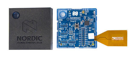
보드 정보는 Nordic Thingy:52 웹사이트에서 확인할 수 있으며, Nordic Thingy:52 guide에는 프로세서 정보와 데이터시트가 들어 있습니다.
하드웨어
Thingy:52의 주요 기능은 다음과 같습니다.
- RGB LED 2개
- CO2 및 TVOC sensor
- Humidity and temperature sensor
- Color sensor
- I2C GPIO expander
- pin header와 I2C/serial connector용 연결부
- Bluetooth radio
지원 기능
| 인터페이스 | 컨트롤러 | 드라이버/컴포넌트 |
|---|---|---|
ADC | on-chip | adc |
CLOCK | on-chip | clock_control |
FLASH | on-chip | flash |
Gas Sensor | on-board | ccs811 |
GPIO | on-chip | gpio |
GPIO Exp | on-board | sx1509b |
Humidity and Temp | on-board | hts221 |
I2C(M) | on-chip | i2c |
MPU | on-chip | arch/arm |
NVIC | on-chip | arch/arm |
Pressure and Temp | on-board | lps22hb_press |
PWM | on-chip | pwm |
RADIO | on-chip | Bluetooth |
RTC | on-chip | system clock |
SPI(M/S) | on-chip | spi |
UART | on-chip | serial |
WDT | on-chip | watchdog |
연결과 입출력
Lightwell RGB LED
LED는 device name이 GPIO_P0인 SX1509B GPIO expander chip으로 구동됩니다.
| GPIO Expander Pin | LED Channel |
|---|---|
5 | Green |
6 | Blue |
7 | Red |
Button
Thingy:52에는 SoC GPIO pin P0.11에 연결된 pushbutton이 있습니다.
Serial
기본 system UART pin 구성은 다음과 같습니다. 이 pin은 P4와 P6 connector에서 찾을 수 있으며 system UART console이 기본으로 사용합니다.
| SOC Pin | Signal |
|---|---|
P0.02 | TX |
P0.03 | RX |
Internal I2C bus
Internal I2C bus(I2C_0)는 외부 connector로 route되지 않지만 대부분의 on-board device가 이 bus를 통해 접근됩니다. 할당된 pin은 다음과 같습니다.
| SOC Pin | Signal |
|---|---|
P0.07 | SDA |
P0.08 | SCL |
bus에 연결된 device와 address는 다음과 같습니다.
| Device | Address |
|---|---|
SX1509B | 0x3e |
LPS22HB | 0x5c |
HTS221 | 0x5f |
CCS811 | 0x5a |
External I2C bus
External I2C bus(I2C_1)는 P4 header와 P5·P7 connector에서 사용할 수 있습니다.
| SOC Pin | Signal |
|---|---|
P0.14 | SDA_EXT |
P0.15 | SCL_EXT |
P4 pin header
P4 pin header를 통해 일부 SoC GPIO pin과 I2C GPIO expander pin에 접근할 수 있고, 외부 device를 보드의 N-channel MOSFET transistor 네 개에 연결할 수도 있습니다.
| Pin | Device | Signal / Device Pin |
|---|---|---|
1 | SOC | SCL_EXT / P0.15 |
2 | SOC | SDA_EXT / P0.14 |
3 | SOC | ANA/DIG0 / P0.02 |
4 | SOC | ANA/DIG1 / P0.03 |
5 | SOC | ANA/DIG2 / P0.04 |
6 | GND | |
7 | GPIO Expander | Pin 0 |
8 | GPIO Expander | Pin 1 |
9 | GPIO Expander | Pin 2 |
10 | GPIO Expander | Pin 3 |
11 | MOSFET 1 | Drain |
12 | MOSFET 1 | Source |
13 | MOSFET 2 | Drain |
14 | MOSFET 2 | Source |
15 | MOSFET 3 | Drain |
16 | MOSFET 3 | Source |
17 | MOSFET 4 | Drain |
18 | MOSFET 4 | Source |
19 | VDD | |
20 | GND |
MOSFET
MOSFET gate가 연결된 SoC GPIO pin은 다음과 같습니다.
| Device | Gate Pin |
|---|---|
MOSFET 1 | P0.18 |
MOSFET 2 | P0.19 |
MOSFET 3 | P0.20 |
MOSFET 4 | P0.21 |
Power rail
Thingy:52에는 여러 power rail이 있으며 현재 지원되는 device에 필요한 rail은 다음과 같습니다.
| Name | Derived from | Controlled by |
|---|---|---|
VREG | The battery | Always on |
VDD_nRF | VREG | Always on |
VDD | VREG | SOC pin P0.30 |
VDD_CCS | VDD | GPIO expander pin 10 |
rail 사이에 dependency가 있으므로 특정 device를 켜려면 여러 rail에 전원을 공급해야 할 수 있습니다. 전원을 켜는 순서는 dependency chain의 위에서 아래 순서입니다. 예를 들어 CCS811 gas sensor를 켜려면 먼저 VDD를 켜고 그 다음 VDD_CCS를 켜야 합니다.
| Device | Rail |
|---|---|
nRF52832 | VDD_nRF |
SX1509B | VDD |
LPS22HB | VDD |
HTS221 | VDD |
CCS811 | VDD_CCS |
Sensor
| Device | Function | Bus | I2C Address | Power Rail |
|---|---|---|---|---|
LPS22HB | Pressure and Temperature sensor | I2C_0 | 0x5c | VDD |
HTS221 | Humidity and Temperature sensor | I2C_0 | 0x5f | VDD |
CCS811 | Gas sensor | I2C_0 | 0x5a | VDD_CCS |
기타 device pin
SX1509B
| Device Signal | SOC Pin |
|---|---|
SX_OSCIO | P0.05 |
SX_RESET | P0.16 |
LPS22HB
| Sensor Signal | SOC Pin |
|---|---|
LPS_INT | P0.23 |
HTS221
| Sensor Signal | SOC Pin |
|---|---|
HTS_INT | P0.24 |
CCS811
| Sensor Signal | GPIO Expander Pin |
|---|---|
CCS_RESET | 11 |
CCS_WAKE | 12 |
프로그래밍과 디버깅
Flash
Thingy:52에 Zephyr를 flash하려면 외부 J-Link programmer가 필요합니다. programmer는 P9 programming header에 연결합니다.
Debug
Thingy:52에는 다른 일부 nRF5 development board와 달리 on-board J-Link debug IC가 없습니다. 따라서 Nordic Segger 절차에 더해 외부 debugger를 연결해야 합니다. Debug out connector가 있는 nRF52 DK 같은 development board를 Thingy:52 debugger로 사용할 수 있습니다.
보드 기능 시험
녹색 lightwell LED는 blinky 예제로 시험할 수 있습니다.
# From the root of the zephyr repository
west build -b thingy52/nrf52832 samples/basic/blinky
west flash
Temperature and humidity sensor는 hts221 sample로 시험할 수 있습니다.
# From the root of the zephyr repository
west build -b thingy52/nrf52832 samples/sensor/hts221
west flash
Source
출처
영어 원문에는 문단, 문서 지시문, 표, 코드, 코드 심벌, 경로를 그대로 보존했습니다.