Part 1
요약·해설
ARMv8-M Cortex-M33F의 셀룰러·DECT NR+ 기능과 보드 입출력을 정리하고, IDAU/SPU 보안 경계에서 Zephyr 또는 TF-M Secure image를 만드는 절차를 설명합니다.
PCA10165
DECT NR+ · LTE-M/NB-IoT
GNSS
Part 2
접을 수 있는 영어 원문 전체
영어 원문 전체 펼치기
3566975DE9087ECA33473091358F3405EF1D9A6BFD95B1DB1FAAFA8F6766FA6E
.. _nrf9131ek_nrf9131:

nRF9131 EK
##########

Overview
********

The nRF9131 EK (PCA10165) is a single-board evaluation kit for the nRF9131 SiP
for DECT NR+ and LTE-M/NB-IoT with GNSS.
The ``nrf9131ek/nrf9131`` board configuration provides support for the Nordic Semiconductor nRF9131 ARM
Cortex-M33F CPU with ARMv8-M Security Extension and the following devices:

* :abbr:`ADC (Analog to Digital Converter)`
* CLOCK
* FLASH
* :abbr:`GPIO (General Purpose Input Output)`
* :abbr:`I2C (Inter-Integrated Circuit)`
* :abbr:`MPU (Memory Protection Unit)`
* :abbr:`NVIC (Nested Vectored Interrupt Controller)`
* :abbr:`PWM (Pulse Width Modulation)`
* :abbr:`RTC (nRF RTC System Clock)`
* Segger RTT (RTT Console)
* :abbr:`SPI (Serial Peripheral Interface)`
* :abbr:`UARTE (Universal asynchronous receiver-transmitter with EasyDMA)`
* :abbr:`WDT (Watchdog Timer)`
* :abbr:`IDAU (Implementation Defined Attribution Unit)`

.. figure:: ../../../../../../../boards/nordic/nrf9131ek/doc/img/nrf9131ek_nrf9131.webp
     :align: center
     :alt: nRF9131 EK

     nRF9131 EK (Credit: Nordic Semiconductor)

The `Nordic Semiconductor TechDocs`_ will soon
contain the processor's information and the datasheet.


Hardware
********

nRF9131 EK has two external oscillators. The frequency of
the slow clock is 32.768 kHz. The frequency of the main clock
is 32 MHz.

Supported Features
==================

The ``nrf9131ek/nrf9131`` board configuration supports the following
hardware features:

+-----------+------------+----------------------+
| Interface | Controller | Driver/Component     |
+===========+============+======================+
| ADC       | on-chip    | adc                  |
+-----------+------------+----------------------+
| CLOCK     | on-chip    | clock_control        |
+-----------+------------+----------------------+
| FLASH     | on-chip    | flash                |
+-----------+------------+----------------------+
| GPIO      | on-chip    | gpio                 |
+-----------+------------+----------------------+
| I2C(M)    | on-chip    | i2c                  |
+-----------+------------+----------------------+
| MPU       | on-chip    | arch/arm             |
+-----------+------------+----------------------+
| NVIC      | on-chip    | arch/arm             |
+-----------+------------+----------------------+
| PWM       | on-chip    | pwm                  |
+-----------+------------+----------------------+
| RTC       | on-chip    | system clock         |
+-----------+------------+----------------------+
| RTT       | Segger     | console              |
+-----------+------------+----------------------+
| SPI(M/S)  | on-chip    | spi                  |
+-----------+------------+----------------------+
| SPU       | on-chip    | system protection    |
+-----------+------------+----------------------+
| UARTE     | on-chip    | serial               |
+-----------+------------+----------------------+
| WDT       | on-chip    | watchdog             |
+-----------+------------+----------------------+

Connections and IOs
===================

LED
---

* LED (red) = P0.29
* LED (green) = P0.30
* LED (blue) = P0.31

Push buttons and Switches
-------------------------

* BUTTON = P0.28
* RESET

Security components
===================

- Implementation Defined Attribution Unit (`IDAU`_).  The IDAU is implemented
  with the System Protection Unit and is used to define secure and non-secure
  memory maps.  By default, all of the memory space  (Flash, SRAM, and
  peripheral address space) is defined to be secure accessible only.
- Secure boot.


Programming and Debugging
*************************

``nrf9131ek/nrf9131`` supports the Armv8m Security Extension, and by default boots
in the Secure state.

Building Secure/Non-Secure Zephyr applications with Arm |reg| TrustZone |reg|
=============================================================================

Applications on the nRF9131 may contain a Secure and a Non-Secure firmware
image. The Secure image can be built using either Zephyr or
`Trusted Firmware M`_ (TF-M). Non-Secure firmware images are always built
using Zephyr. The two alternatives are described below.

.. note::

   By default the Secure image for nRF9131 is built using TF-M.

Building the Secure firmware using Zephyr
-----------------------------------------

The process requires the following steps:

1. Build the Secure Zephyr application using ``-DBOARD=nrf9131ek/nrf9131`` and
   ``CONFIG_TRUSTED_EXECUTION_SECURE=y`` in the application project configuration file.
2. Build the Non-Secure Zephyr application using ``-DBOARD=nrf9131ek/nrf9131/ns``.
3. Merge the two binaries together.

Building the Secure firmware with TF-M
--------------------------------------

The process to build the Secure firmware image using TF-M and the Non-Secure
firmware image using Zephyr requires the following action:

1. Build the Non-Secure Zephyr application
   using ``-DBOARD=nrf9131ek/nrf9131/ns``.
   To invoke the building of TF-M the Zephyr build system requires the
   Kconfig option ``BUILD_WITH_TFM`` to be enabled, which is done by
   default when building Zephyr as a Non-Secure application.
   The Zephyr build system will perform the following steps automatically:

      * Build the Non-Secure firmware image as a regular Zephyr application
      * Build a TF-M (secure) firmware image
      * Merge the output binaries together
      * Optionally build a bootloader image (MCUboot)

.. note::

   Depending on the TF-M configuration, an application DTS overlay may be
   required, to adjust the Non-Secure image Flash and SRAM starting address
   and sizes.

When building a Secure/Non-Secure application, the Secure application will
have to set the IDAU (SPU) configuration to allow Non-Secure access to all
CPU resources utilized by the Non-Secure application firmware. SPU
configuration shall take place before jumping to the Non-Secure application.

Building a Secure only application
==================================

Build the Zephyr app in the usual way (see :ref:`build_an_application`
and :ref:`application_run`), using ``-DBOARD=nrf9131ek/nrf9131``.


Flashing
========

Follow the instructions in the :ref:`nordic_segger` page to install
and configure all the necessary software. Further information can be
found in :ref:`nordic_segger_flashing`. Then build and flash
applications as usual (see :ref:`build_an_application` and
:ref:`application_run` for more details).

Here is an example for the :ref:`hello_world` application.

First, run your favorite terminal program to listen for output.

.. code-block:: console

   $ minicom -D <tty_device> -b 115200

Replace :code:`<tty_device>` with the port where the nRF9131 EK
can be found. For example, under Linux, :code:`/dev/ttyACM0`.

Then build and flash the application in the usual way.

.. zephyr-app-commands::
   :zephyr-app: samples/hello_world
   :board: nrf9131ek/nrf9131
   :goals: build flash

Debugging
=========

Refer to the :ref:`nordic_segger` page to learn about debugging Nordic boards with a
Segger IC.


Testing the LEDs and buttons in the nRF9131 EK
**********************************************

There are 2 samples that allow you to test that the button and LED on
the board are working properly with Zephyr:

* :zephyr:code-sample:`blinky`
* :zephyr:code-sample:`button`

You can build and flash the examples to make sure Zephyr is running correctly on
your board. The button and LED definitions can be found in
:zephyr_file:`boards/nordic/nrf9131ek/nrf9131ek_nrf9131_common.dtsi`.

References
**********

.. target-notes::

.. _IDAU:
   https://developer.arm.com/docs/100690/latest/attribution-units-sau-and-idau
.. _Nordic Semiconductor TechDocs: https://docs.nordicsemi.com/
.. _Trusted Firmware M: https://www.trustedfirmware.org/projects/tf-m/
Part 3
한국어 전문 번역
개요
nRF9131 EK(PCA10165)는 DECT NR+와 LTE-M/NB-IoT, GNSS를 지원하는 nRF9131 SiP용 single-board evaluation kit입니다.
nrf9131ek/nrf9131 보드 구성은 ARMv8-M Security Extension을 갖춘 Nordic Semiconductor nRF9131 ARM Cortex-M33F CPU와 다음 장치를 지원합니다.
- ADC(Analog to Digital Converter)
- CLOCK
- FLASH
- GPIO(General Purpose Input Output)
- I2C(Inter-Integrated Circuit)
- MPU(Memory Protection Unit)
- NVIC(Nested Vectored Interrupt Controller)
- PWM(Pulse Width Modulation)
- RTC(nRF RTC System Clock)
- Segger RTT(RTT Console)
- SPI(Serial Peripheral Interface)
- UARTE(Universal asynchronous receiver-transmitter with EasyDMA)
- WDT(Watchdog Timer)
- IDAU(Implementation Defined Attribution Unit)
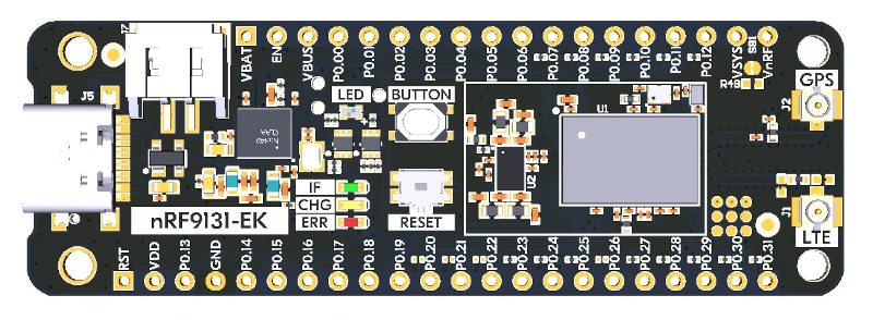
Nordic Semiconductor TechDocs에는 향후 프로세서 정보와 데이터시트가 제공될 예정입니다.
하드웨어
nRF9131 EK에는 외부 oscillator가 두 개 있습니다. 저속 clock의 주파수는 32.768 kHz이고 main clock의 주파수는 32 MHz입니다.
지원 기능
nrf9131ek/nrf9131 보드 구성이 지원하는 하드웨어 기능은 다음과 같습니다.
| 인터페이스 | 컨트롤러 | 드라이버/컴포넌트 |
|---|---|---|
ADC | on-chip | adc |
CLOCK | on-chip | clock_control |
FLASH | on-chip | flash |
GPIO | on-chip | gpio |
I2C(M) | on-chip | i2c |
MPU | on-chip | arch/arm |
NVIC | on-chip | arch/arm |
PWM | on-chip | pwm |
RTC | on-chip | system clock |
RTT | Segger | console |
SPI(M/S) | on-chip | spi |
SPU | on-chip | system protection |
UARTE | on-chip | serial |
WDT | on-chip | watchdog |
연결과 입출력
LED
- LED(빨간색) =
P0.29 - LED(녹색) =
P0.30 - LED(파란색) =
P0.31
Push button과 switch
- BUTTON =
P0.28 - RESET
보안 컴포넌트
- IDAU: Implementation Defined Attribution Unit은 System Protection Unit(SPU)으로 구현되며 Secure memory map과 Non-Secure memory map을 정의하는 데 사용됩니다. 기본 상태에서는 Flash, SRAM, peripheral address space를 포함한 모든 memory space가 Secure 상태에서만 접근할 수 있게 정의됩니다.
- Secure boot: 보드가 Secure한 부팅 흐름을 구성할 수 있도록 지원합니다.
프로그래밍과 디버깅
nrf9131ek/nrf9131은 Armv8-M Security Extension을 지원하며 기본적으로 Secure state에서 부팅합니다.
Arm TrustZone으로 Secure/Non-Secure Zephyr 애플리케이션 빌드
nRF9131 애플리케이션에는 Secure firmware image와 Non-Secure firmware image가 함께 들어갈 수 있습니다. Secure image는 Zephyr 또는 Trusted Firmware-M(TF-M)으로 빌드할 수 있지만, Non-Secure firmware image는 항상 Zephyr로 빌드합니다.
Zephyr로 Secure firmware 빌드
-DBOARD=nrf9131ek/nrf9131을 사용하고 애플리케이션 project configuration file에CONFIG_TRUSTED_EXECUTION_SECURE=y를 설정하여 Secure Zephyr 애플리케이션을 빌드합니다.-DBOARD=nrf9131ek/nrf9131/ns를 사용해 Non-Secure Zephyr 애플리케이션을 빌드합니다.- 두 binary를 병합합니다.
TF-M으로 Secure firmware 빌드
TF-M Secure firmware image와 Zephyr Non-Secure firmware image를 만드는 절차에서는 다음 작업을 수행합니다.
-DBOARD=nrf9131ek/nrf9131/ns를 사용해 Non-Secure Zephyr 애플리케이션을 빌드합니다.Zephyr build system이 TF-M 빌드를 호출하려면 Kconfig 옵션
BUILD_WITH_TFM이 활성화되어야 합니다. Zephyr를 Non-Secure 애플리케이션으로 빌드할 때 이 옵션은 기본으로 활성화됩니다. Zephyr build system은 다음 작업을 자동으로 수행합니다.- 일반 Zephyr 애플리케이션과 같은 방식으로 Non-Secure firmware image 빌드
- TF-M Secure firmware image 빌드
- 두 출력 binary 병합
- 선택적으로 MCUboot bootloader image 빌드
Secure/Non-Secure 애플리케이션을 빌드할 때 Secure 애플리케이션은 Non-Secure application firmware가 사용하는 모든 CPU resource에 Non-Secure access를 허용하도록 IDAU(SPU)를 구성해야 합니다. 이 SPU 구성은 Non-Secure 애플리케이션으로 제어를 넘기기 전에 완료해야 합니다.
Secure-only 애플리케이션 빌드
-DBOARD=nrf9131ek/nrf9131을 사용하여 일반적인 Zephyr 애플리케이션 빌드 및 실행 방법으로 빌드합니다.
Flash
Nordic Segger 안내에 따라 필요한 소프트웨어를 설치하고 구성한 뒤 일반적인 방식으로 애플리케이션을 빌드하고 flash합니다. 다음은 hello_world 예입니다.
먼저 원하는 terminal 프로그램으로 출력을 수신합니다.
$ minicom -D <tty_device> -b 115200<tty_device>를 nRF9131 EK가 연결된 port로 바꾸십시오. Linux에서는 예를 들어 /dev/ttyACM0입니다. 그런 다음 일반적인 방식으로 애플리케이션을 빌드하고 flash합니다.
# From the root of the zephyr repository
west build -b nrf9131ek/nrf9131 samples/hello_world
west flash
Debug
Segger IC를 이용한 Nordic 보드 디버깅 방법은 Nordic Segger 문서를 참고하십시오.
nRF9131 EK의 LED와 버튼 시험
다음 두 sample을 사용하면 보드의 button과 LED가 Zephyr에서 올바르게 동작하는지 시험할 수 있습니다.
samples/basic/blinkysamples/basic/button
예제를 빌드하고 flash하면 보드에서 Zephyr가 정상 실행되는지 확인할 수 있습니다. 버튼과 LED 정의는 boards/nordic/nrf9131ek/nrf9131ek_nrf9131_common.dtsi에서 확인할 수 있습니다.
Source
출처
영어 원문에는 문단, 문서 지시문, 표, 코드, 코드 심벌, 경로를 그대로 보존했습니다.