Part 1
요약·해설
세 flash 경로는 bootloader와 partition 전제가 다릅니다. 내장 DFU는 nrfutil, MCUboot 복구는 mcumgr, 외부 probe는 SWD header와 DTS/Kconfig 변경을 사용합니다.
PCA10059
nrfutil · USB serial
MCUboot · mcumgr
Part 2
접을 수 있는 영어 원문 전체
영어 원문 전체 펼치기
5DD80A4A113313728EE500CDEFD3457618740434494DA796A3ED8AABB22C4241
.. _nrf52840dongle_nrf52840:

nRF52840 Dongle
###############

Overview
********

The nRF52840 Dongle (PCA10059) hardware provides support for the Nordic
Semiconductor nRF52840 ARM Cortex-M4F CPU and the following devices:

* :abbr:`ADC (Analog to Digital Converter)`
* CLOCK
* FLASH
* :abbr:`GPIO (General Purpose Input Output)`
* :abbr:`I2C (Inter-Integrated Circuit)`
* :abbr:`MPU (Memory Protection Unit)`
* :abbr:`NVIC (Nested Vectored Interrupt Controller)`
* :abbr:`PWM (Pulse Width Modulation)`
* RADIO (Bluetooth Low Energy and 802.15.4)
* :abbr:`RTC (nRF RTC System Clock)`
* :abbr:`SPI (Serial Peripheral Interface)`
* :abbr:`UART (Universal asynchronous receiver-transmitter)`
* :abbr:`USB (Universal Serial Bus)`
* :abbr:`WDT (Watchdog Timer)`

.. figure:: ../../../../../../../boards/nordic/nrf52840dongle/doc/img/nrf52840dongle_nrf52840.jpg
     :align: center
     :alt: nRF52840 Dongle

     nRF52840 Dongle

More information about the board can be found at the
`nRF52840 Dongle website`_. The `nRF52840 Dongle guide`_
contains the processor's information and the datasheet.


Hardware
********

The ``nrf52840dongle/nrf52840`` has two external oscillators. The frequency of
the slow clock is 32.768 kHz. The frequency of the main clock
is 32 MHz.

Supported Features
==================

The ``nrf52840dongle/nrf52840`` board configuration supports the following
hardware features:

+-----------+------------+----------------------+
| Interface | Controller | Driver/Component     |
+===========+============+======================+
| ADC       | on-chip    | adc                  |
+-----------+------------+----------------------+
| CLOCK     | on-chip    | clock_control        |
+-----------+------------+----------------------+
| FLASH     | on-chip    | flash                |
+-----------+------------+----------------------+
| GPIO      | on-chip    | gpio                 |
+-----------+------------+----------------------+
| I2C(M)    | on-chip    | i2c                  |
+-----------+------------+----------------------+
| MPU       | on-chip    | arch/arm             |
+-----------+------------+----------------------+
| NVIC      | on-chip    | arch/arm             |
+-----------+------------+----------------------+
| PWM       | on-chip    | pwm                  |
+-----------+------------+----------------------+
| RADIO     | on-chip    | Bluetooth,           |
|           |            | ieee802154           |
+-----------+------------+----------------------+
| RTC       | on-chip    | system clock         |
+-----------+------------+----------------------+
| SPI(M/S)  | on-chip    | spi                  |
+-----------+------------+----------------------+
| UART      | on-chip    | serial               |
+-----------+------------+----------------------+
| USB       | on-chip    | usb                  |
+-----------+------------+----------------------+
| WDT       | on-chip    | watchdog             |
+-----------+------------+----------------------+

Other hardware features have not been enabled yet for this board.
See `nRF52840 Dongle website`_ and `nRF52840 Dongle Hardware description`_
for a complete list of nRF52840 Dongle board hardware features.

Connections and IOs
===================

LED
---

* LED0 (green) = P0.6
* LED1 (red)   = P0.8
* LED1 (green) = P1.9
* LED1 (blue)  = P0.12

Push buttons
------------

* BUTTON1 = SW1 = P1.6
* RESET   = SW2 = P0.18

Programming and Debugging
*************************

Applications for the ``nrf52840dongle/nrf52840`` board configuration can be
built in the usual way (see :ref:`build_an_application` for more details).

Flashing
========

The board supports the following programming options:

1. Using the built-in bootloader only
2. Using MCUboot in serial recovery mode
3. Using an external :ref:`debug probe <debug-probes>`

These instructions use the :ref:`west <west>` tool and assume you are in the
root directory of your :term:`west installation`.

Option 1: Using the Built-In Bootloader Only
--------------------------------------------

The board is factory-programmed with Nordic's bootloader from Nordic's nRF5
SDK. With this option, you'll use Nordic's `nrfutil`_ program to create
firmware packages supported by this bootloader and flash them to the
device. Make sure ``nrfutil`` is installed before proceeding.

#. Reset the board into the Nordic bootloader by pressing the RESET button.

   The push button is on the far side of the board from the USB connector. Note
   that the button does not face up. You will have to push it from the outside
   in, towards the USB connector:

   .. image:: ../../../../../../../boards/nordic/nrf52840dongle/doc/img/nRF52840_dongle_press_reset.svg
      :alt: Location of RESET button and direction of push

   The red LED should start a fade pattern, signalling the bootloader is
   running.

#. Compile a Zephyr application; we'll use :zephyr:code-sample:`blinky`.

   .. zephyr-app-commands::
      :app: zephyr/samples/basic/blinky
      :board: nrf52840dongle/nrf52840
      :goals: build

#. Package the application for the bootloader using ``nrfutil``:

   .. code-block:: console

      nrfutil pkg generate --hw-version 52 --sd-req=0x00 \
              --application build/zephyr/zephyr.hex \
              --application-version 1 blinky.zip

#. Flash it onto the board. Note :file:`/dev/ttyACM0` is for Linux; it will be
   something like ``COMx`` on Windows, and something else on macOS.

   .. code-block:: console

      nrfutil dfu usb-serial -pkg blinky.zip -p /dev/ttyACM0

   When this command exits, observe the green LED on the board blinking,
   instead of the red LED used by the bootloader.

For more information, see `Nordic Semiconductor USB DFU`_.

Option 2: Using MCUboot in Serial Recovery Mode
-----------------------------------------------

It is also possible to use the MCUboot bootloader with this board to flash
Zephyr applications. You need to do some one-time set-up to build and flash
MCUboot on your board. From that point on, you can build and flash other Zephyr
applications using MCUboot's serial recovery mode. This process does not
overwrite the built-in Nordic bootloader, so you can always go back to using
Option 1 later.

Install `nrfutil`_ and `mcumgr`_ first, and make sure MCUboot's ``imgtool`` is
available for signing your binary for MCUboot as described on :ref:`west-sign`.

Next, do the **one-time setup** to flash MCUboot. We'll assume you've cloned
the `MCUboot`_ repository into the directory ``mcuboot``, and that it is next
to the zephyr repository on your computer.

#. Reset the board into the Nordic bootloader as described above.

#. Compile MCUboot as a Zephyr application.

   .. zephyr-app-commands::
      :app: mcuboot/boot/zephyr
      :board: nrf52840dongle/nrf52840
      :build-dir: mcuboot
      :goals: build

#. Package the application for the bootloader using ``nrfutil``:

   .. code-block:: console

      nrfutil pkg generate --hw-version 52 --sd-req=0x00 \
              --application build/mcuboot/zephyr/zephyr.hex \
              --application-version 1 mcuboot.zip

#. Flash it onto the board. Note :file:`/dev/ttyACM0` is for Linux; it will be
   something like ``COMx`` on Windows, and something else on macOS.

   .. code-block:: console

      nrfutil dfu usb-serial -pkg mcuboot.zip -p /dev/ttyACM0

You can now flash a Zephyr application to the board using MCUboot's serial
recovery mode. We'll use the :zephyr:code-sample:`smp-svr` sample since it's ready to be
compiled for chain-loading by MCUboot (and itself supports firmware updates
over Bluetooth).

#. Boot into MCUboot serial recovery mode by plugging the board in with the SW1
   button pressed down. See above for a picture showing where SW1 is.

   **Do not press RESET**; that will run the Nordic bootloader, which is
   different than MCUboot.

   A serial port will enumerate on your board. On Windows, "MCUBOOT" should
   appear under "Other Devices" in the Device Manager (in addition to the usual
   ``COMx`` device). On Linux, something like
   :file:`/dev/serial/by-id/usb-ZEPHYR_MCUBOOT_0.01-if00` should be created.

   If no serial port appears, try plugging it in again, making sure SW1 is
   pressed. If it still doesn't appear, retry the one-time MCUboot setup.

#. Compile ``smp_svr``.

   .. zephyr-app-commands::
      :app: zephyr/samples/subsys/mgmt/mcumgr/smp_svr
      :board: nrf52840dongle/nrf52840
      :build-dir: smp_svr
      :goals: build

#. Sign ``smp_svr`` for chain-loading by MCUboot.

   .. code-block:: console

      west sign -t imgtool --bin --no-hex -d build/smp_svr \
                -B smp_svr.signed.bin -- --key mcuboot/root-rsa-2048.pem

#. Flash the application to the MCUboot serial port using ``mcumgr``:

   .. code-block:: console

      mcumgr --conntype=serial --connstring='dev=/dev/ttyACM0,baud=115200' \
             image upload -e smp_svr.signed.bin

#. Reset the device:

   .. code-block:: console

      mcumgr --conntype=serial --connstring='dev=/dev/ttyACM0,baud=115200' reset

You should now be able to scan for Bluetooth devices using a smartphone or
computer. The device you just flashed will be listed with ``Zephyr`` in its
name.

.. note::

   This board supports building other Zephyr applications for flashing with
   MCUboot in this way also. Just make sure :kconfig:option:`CONFIG_BOOTLOADER_MCUBOOT`
   is set when building your application. For example, to compile blinky for
   loading by MCUboot, use this:

   .. zephyr-app-commands::
      :app: zephyr/samples/basic/blinky
      :board: nrf52840dongle/nrf52840
      :build-dir: blinky
      :goals: build
      :gen-args: -DCONFIG_BOOTLOADER_MCUBOOT=y

   You can then sign and flash it using the steps above.

Option 3: Using an External Debug Probe
---------------------------------------

If you have one, you can also use an external :ref:`debug probe <debug-probes>`
to flash and debug Zephyr applications, but you need to solder an SWD header
onto the back side of the board.

For Segger J-Link debug probes, follow the instructions in the
:ref:`nordic_segger` page to install and configure all the necessary
software. Further information can be found in :ref:`nordic_segger_flashing`.

Locate the DTS file: :zephyr_file:`boards/nordic/nrf52840dongle/nrf52840dongle_nrf52840.dts`.
This file requires a small modification to use a different partition table.
Edit the include directive to include "fstab-debugger" instead of "fstab-stock".

In addition, the Kconfig file in the same directory must be modified by setting
``BOARD_HAS_NRF5_BOOTLOADER`` to be default ``n``, otherwise the code will be
flashed with an offset.

Then build and flash applications as usual (see :ref:`build_an_application` and
:ref:`application_run` for more details).

Here is an example for the :zephyr:code-sample:`blinky` application.

.. zephyr-app-commands::
   :zephyr-app: samples/basic/blinky
   :board: nrf52840dongle/nrf52840
   :goals: build flash

Observe the LED on the board blinking.

Debugging
=========

The ``nrf52840dongle/nrf52840`` board does not have an on-board J-Link debug IC
as some nRF5x development boards, however, instructions from the
:ref:`nordic_segger` page also apply to this board, with the additional step
of connecting an external debugger.

Testing the LEDs and buttons on the nRF52840 Dongle
***************************************************

There are 2 samples that allow you to test that the buttons (switches) and LEDs on
the board are working properly with Zephyr:

* :zephyr:code-sample:`blinky`

You can build and program the examples to make sure Zephyr is running correctly
on your board.


References
**********

.. target-notes::

.. _nRF52840 Dongle website:
   https://www.nordicsemi.com/Software-and-Tools/Development-Kits/nRF52840-Dongle
.. _nRF52840 Dongle guide: https://docs.nordicsemi.com/bundle/ug_nrf52840_dk/page/UG/dk/intro.html
.. _nRF52840 Dongle Hardware description: https://docs.nordicsemi.com/bundle/ug_nrf52840_dongle/page/UG/nrf52840_Dongle/hw_description.html
.. _J-Link Software and documentation pack:
   https://www.segger.com/jlink-software.html
.. _Nordic Semiconductor USB DFU:
   https://docs.nordicsemi.com/bundle/sdk_nrf5_v17.1.0/page/sdk_app_serial_dfu_bootloader.html
.. _nrfutil:
   https://github.com/NordicSemiconductor/pc-nrfutil
.. _MCUboot:
   https://github.com/JuulLabs-OSS/mcuboot
.. _mcumgr:
   https://github.com/apache/mynewt-mcumgr-cli
Part 3
한국어 전문 번역
개요
nRF52840 Dongle(PCA10059)은 Nordic Semiconductor nRF52840 Arm Cortex-M4F CPU를 탑재하며 ADC, CLOCK, FLASH, GPIO, I2C, MPU, NVIC, PWM, Bluetooth Low Energy와 IEEE 802.15.4용 RADIO, RTC, SPI, UART, USB, WDT를 지원합니다.
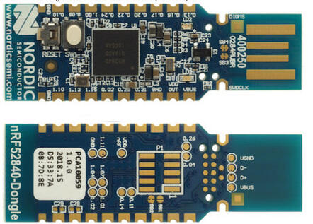
보드 정보는 nRF52840 Dongle 웹사이트에서 확인할 수 있습니다. nRF52840 Dongle guide에는 프로세서 정보와 데이터시트가 들어 있습니다.
하드웨어
nrf52840dongle/nrf52840에는 외부 oscillator가 두 개 있습니다. 저속 clock은 32.768 kHz, main clock은 32 MHz입니다.
지원 기능
nrf52840dongle/nrf52840 보드 구성에서 지원하는 하드웨어 기능은 다음과 같습니다.
| 인터페이스 | 컨트롤러 | 드라이버/컴포넌트 |
|---|---|---|
ADC | on-chip | adc |
CLOCK | on-chip | clock_control |
FLASH | on-chip | flash |
GPIO | on-chip | gpio |
I2C(M) | on-chip | i2c |
MPU | on-chip | arch/arm |
NVIC | on-chip | arch/arm |
PWM | on-chip | pwm |
RADIO | on-chip | Bluetooth, ieee802154 |
RTC | on-chip | system clock |
SPI(M/S) | on-chip | spi |
UART | on-chip | serial |
USB | on-chip | usb |
WDT | on-chip | watchdog |
그 밖의 하드웨어 기능은 아직 이 보드에서 활성화되지 않았습니다. 전체 기능은 nRF52840 Dongle 웹사이트와 nRF52840 Dongle Hardware description을 참고하십시오.
연결과 입출력
LED
- LED0(녹색):
P0.6 - LED1(빨간색):
P0.8 - LED1(녹색):
P1.9 - LED1(파란색):
P0.12
Push button
- BUTTON1 = SW1 =
P1.6 - RESET = SW2 =
P0.18
프로그래밍과 디버깅
nrf52840dongle/nrf52840 보드용 애플리케이션은 일반적인 Zephyr 방식으로 빌드할 수 있습니다.
Flash 방법
보드는 다음 세 가지 프로그래밍 방법을 지원합니다.
- 내장 bootloader만 사용
- MCUboot serial recovery mode 사용
- 외부 debug probe 사용
아래 절차는 west를 사용하며 현재 directory가 west 설치의 root라고 가정합니다.
방법 1: 내장 bootloader만 사용
보드에는 Nordic nRF5 SDK의 Nordic bootloader가 공장 출하 상태로 프로그래밍되어 있습니다. 이 방법에서는 nrfutil로 bootloader가 지원하는 firmware package를 만들고 장치에 flash합니다. 시작하기 전에 nrfutil을 설치하십시오.
RESET 버튼을 눌러 보드를 Nordic bootloader로 reset합니다. 버튼은 USB connector에서 먼 쪽에 있고 위를 향하지 않습니다. 보드 바깥쪽에서 USB connector 쪽 안으로 밀어야 합니다.
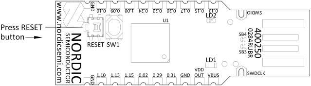
nRF52840 Dongle RESET 버튼의 위치와 누르는 방향. 이미지 출처: Zephyr 3.7.0. bootloader가 실행되면 빨간색 LED가 서서히 밝아졌다 어두워지는 fade pattern을 시작합니다.
Zephyr
blinky애플리케이션을 컴파일합니다.west build -b nrf52840dongle/nrf52840 zephyr/samples/basic/blinkynrfutil로 애플리케이션을 bootloader package로 만듭니다.nrfutil pkg generate --hw-version 52 --sd-req=0x00 \ --application build/zephyr/zephyr.hex \ --application-version 1 blinky.zippackage를 보드에 flash합니다.
/dev/ttyACM0는 Linux 예이며 Windows에서는COMx, macOS에서는 다른 이름을 사용합니다.nrfutil dfu usb-serial -pkg blinky.zip -p /dev/ttyACM0명령이 끝나면 bootloader가 사용하던 빨간색 LED 대신 보드의 녹색 LED가 깜박이는지 확인합니다.
자세한 내용은 Nordic Semiconductor USB DFU를 참고하십시오.
방법 2: MCUboot serial recovery mode 사용
이 보드에서 MCUboot bootloader를 사용해 Zephyr 애플리케이션을 flash할 수도 있습니다. 처음 한 번 MCUboot를 빌드하고 보드에 flash한 뒤에는 MCUboot의 serial recovery mode로 다른 애플리케이션을 빌드하고 flash할 수 있습니다.
먼저 nrfutil과 mcumgr를 설치하고, MCUboot binary 서명을 위해 imgtool을 사용할 수 있게 준비하십시오.
다음은 MCUboot를 flash하는 최초 1회 설정입니다. MCUboot 저장소를 mcuboot directory에 clone했으며 컴퓨터에서 Zephyr 저장소와 나란히 있다고 가정합니다.
- 앞에서 설명한 방법으로 보드를 Nordic bootloader로 reset합니다.
MCUboot를 Zephyr 애플리케이션으로 컴파일합니다.
west build -b nrf52840dongle/nrf52840 -d build/mcuboot mcuboot/boot/zephyrnrfutil로 MCUboot package를 만듭니다.nrfutil pkg generate --hw-version 52 --sd-req=0x00 \ --application build/mcuboot/zephyr/zephyr.hex \ --application-version 1 mcuboot.zippackage를 보드에 flash합니다. port 이름은 운영체제에 맞게 바꾸십시오.
nrfutil dfu usb-serial -pkg mcuboot.zip -p /dev/ttyACM0
이제 MCUboot serial recovery mode로 Zephyr 애플리케이션을 flash할 수 있습니다. 예제는 MCUboot chain-loading용으로 준비되어 있고 Bluetooth firmware update도 지원하는 smp_svr sample입니다.
SW1 버튼을 누른 채 보드를 연결해 MCUboot serial recovery mode로 부팅합니다.
보드에 serial port가 열립니다. Windows Device Manager에서는 일반
COMx장치 외에MCUBOOT가 Other Devices 아래 나타나야 합니다. Linux에서는/dev/serial/by-id/usb-ZEPHYR_MCUBOOT_0.01-if00같은 경로가 만들어집니다.serial port가 없으면 SW1을 확실히 누른 채 다시 연결하십시오. 그래도 나타나지 않으면 최초 1회 MCUboot 설정을 다시 수행합니다.
smp_svr를 컴파일합니다.west build -b nrf52840dongle/nrf52840 -d build/smp_svr zephyr/samples/subsys/mgmt/mcumgr/smp_svrMCUboot가 chain-load할 수 있도록
smp_svr에 서명합니다.west sign -t imgtool --bin --no-hex -d build/smp_svr \ -B smp_svr.signed.bin -- --key mcuboot/root-rsa-2048.pemmcumgr로 애플리케이션을 MCUboot serial port에 upload합니다.mcumgr --conntype=serial --connstring='dev=/dev/ttyACM0,baud=115200' \ image upload -e smp_svr.signed.bin장치를 reset합니다.
mcumgr --conntype=serial --connstring='dev=/dev/ttyACM0,baud=115200' reset
이제 스마트폰이나 컴퓨터에서 Bluetooth 장치를 검색하면 방금 flash한 장치의 이름에 Zephyr가 표시됩니다.
west build -b nrf52840dongle/nrf52840 -d build/blinky zephyr/samples/basic/blinky -- -DCONFIG_BOOTLOADER_MCUBOOT=y그런 다음 앞 절차처럼 서명하고 flash할 수 있습니다.
방법 3: 외부 debug probe 사용
외부 debug probe가 있다면 Zephyr 애플리케이션을 flash하고 debug할 수 있지만 보드 뒷면에 SWD header를 납땜해야 합니다.
Segger J-Link debug probe는 Nordic Segger 안내에 따라 필요한 소프트웨어를 설치하고 구성하십시오.
DTS 파일 boards/nordic/nrf52840dongle/nrf52840dongle_nrf52840.dts에서 다른 partition table을 사용하도록 include directive를 fstab-stock 대신 fstab-debugger로 바꿉니다.
또한 같은 directory의 Kconfig에서 BOARD_HAS_NRF5_BOOTLOADER의 default를 n으로 바꿔야 합니다. 그렇지 않으면 코드가 offset을 두고 flash됩니다.
이후 애플리케이션을 일반적인 방식으로 빌드하고 flash합니다. blinky 예는 다음과 같습니다.
# From the root of the zephyr repository
west build -b nrf52840dongle/nrf52840 samples/basic/blinky
west flash
보드 LED가 깜박이는지 확인합니다.
디버깅
nrf52840dongle/nrf52840 보드에는 일부 nRF5x 개발 보드와 달리 내장 J-Link debug IC가 없습니다. 외부 debugger를 연결한 뒤 Nordic Segger 절차를 적용하십시오.
LED와 버튼 시험
blinky sample을 빌드하고 프로그래밍해 보드에서 LED가 올바르게 동작하고 Zephyr가 정상 실행되는지 확인할 수 있습니다.
Source
출처
영어 원문에는 문단, 문서 지시문, 표, 코드, 코드 심벌, 경로를 그대로 보존했습니다.