Part 1
요약·해설
nrf52840dk/nrf52840으로 보드를 사용하고, 별도 개발 키트가 없는 nRF52811은 nrf52840dk/nrf52811으로 제한을 재현합니다.
PCA10056
nRF52840 · Cortex-M4F
nRF52811
Part 2
접을 수 있는 영어 원문 전체
영어 원문 전체 펼치기
1F20480FAE6382B46131A9680B2D9BEB6F060C1B7E45AD17CCE536A82CEC7BC0
.. _nrf52840dk_nrf52840:

nRF52840 DK
###########

Overview
********

The nRF52840 Development Kit (PCA10056) hardware provides support for the
Nordic Semiconductor nRF52840 ARM Cortex-M4F CPU and the following devices:

* :abbr:`ADC (Analog to Digital Converter)`
* CLOCK
* FLASH
* :abbr:`GPIO (General Purpose Input Output)`
* :abbr:`I2C (Inter-Integrated Circuit)`
* :abbr:`MPU (Memory Protection Unit)`
* :abbr:`NVIC (Nested Vectored Interrupt Controller)`
* :abbr:`PWM (Pulse Width Modulation)`
* RADIO (Bluetooth Low Energy and 802.15.4)
* :abbr:`RTC (nRF RTC System Clock)`
* Segger RTT (RTT Console)
* :abbr:`SPI (Serial Peripheral Interface)`
* :abbr:`UART (Universal asynchronous receiver-transmitter)`
* :abbr:`USB (Universal Serial Bus)`
* :abbr:`WDT (Watchdog Timer)`

.. figure:: ../../../../../../../boards/nordic/nrf52840dk/doc/img/nrf52840dk_nrf52840.jpg
     :align: center
     :alt: nRF52840 DK

     nRF52840 DK (Credit: Nordic Semiconductor)

More information about the board can be found at the `nRF52840 DK website`_.
`nRF52840 Product Specification`_ contains the processor's information
and the datasheet.


Hardware
********

nRF52840 DK has two external oscillators. The frequency of the slow clock
is 32.768 kHz. The frequency of the main clock is 32 MHz.

Supported Features
==================

The ``nrf52840dk/nrf52840`` board configuration supports the following
hardware features:

+-----------+------------+----------------------+
| Interface | Controller | Driver/Component     |
+===========+============+======================+
| ADC       | on-chip    | adc                  |
+-----------+------------+----------------------+
| CLOCK     | on-chip    | clock_control        |
+-----------+------------+----------------------+
| FLASH     | on-chip    | flash                |
+-----------+------------+----------------------+
| GPIO      | on-chip    | gpio                 |
+-----------+------------+----------------------+
| I2C(M)    | on-chip    | i2c                  |
+-----------+------------+----------------------+
| MPU       | on-chip    | arch/arm             |
+-----------+------------+----------------------+
| NVIC      | on-chip    | arch/arm             |
+-----------+------------+----------------------+
| PWM       | on-chip    | pwm                  |
+-----------+------------+----------------------+
| RADIO     | on-chip    | Bluetooth,           |
|           |            | ieee802154           |
+-----------+------------+----------------------+
| RTC       | on-chip    | system clock         |
+-----------+------------+----------------------+
| RTT       | Segger     | console              |
+-----------+------------+----------------------+
| SPI(M/S)  | on-chip    | spi                  |
+-----------+------------+----------------------+
| UART      | on-chip    | serial               |
+-----------+------------+----------------------+
| USB       | on-chip    | usb                  |
+-----------+------------+----------------------+
| WDT       | on-chip    | watchdog             |
+-----------+------------+----------------------+

Other hardware features have not been enabled yet for this board.
See `nRF52840 DK website`_ and `nRF52840 DK Hardware guide`_
for a complete list of nRF52840 Development Kit board hardware features.

Connections and IOs
===================

LED
---

* LED1 (green) = P0.13
* LED2 (green) = P0.14
* LED3 (green) = P0.15
* LED4 (green) = P0.16

Push buttons
------------

* BUTTON1 = SW1 = P0.11
* BUTTON2 = SW2 = P0.12
* BUTTON3 = SW3 = P0.24
* BUTTON4 = SW4 = P0.25
* BOOT = SW5 = boot/reset

Programming and Debugging
*************************

Applications for the ``nrf52840dk/nrf52840`` board configuration can be
built, flashed, and debugged in the usual way. See
:ref:`build_an_application` and :ref:`application_run` for more details on
building and running.

Flashing
========

Follow the instructions in the :ref:`nordic_segger` page to install
and configure all the necessary software. Further information can be
found in :ref:`nordic_segger_flashing`. Then build and flash
applications as usual (see :ref:`build_an_application` and
:ref:`application_run` for more details).

Here is an example for the :ref:`hello_world` application.

First, run your favorite terminal program to listen for output.

.. code-block:: console

   $ minicom -D <tty_device> -b 115200

Replace :code:`<tty_device>` with the port where the board nRF52840 DK
can be found. For example, under Linux, :code:`/dev/ttyACM0`.

Then build and flash the application in the usual way.

.. zephyr-app-commands::
   :zephyr-app: samples/hello_world
   :board: nrf52840dk/nrf52840
   :goals: build flash

Debugging
=========

Refer to the :ref:`nordic_segger` page to learn about debugging Nordic boards with a
Segger IC.


Testing the LEDs and buttons in the nRF52840 DK
***********************************************

There are 2 samples that allow you to test that the buttons (switches) and LEDs on
the board are working properly with Zephyr:

.. code-block:: console

   samples/basic/blinky
   samples/basic/button

You can build and flash the examples to make sure Zephyr is running correctly on
your board. The button and LED definitions can be found in
:zephyr_file:`boards/nordic/nrf52840dk/nrf52840dk_nrf52840.dts`.

Changing UART1 pins
*******************

The following approach can be used when an application needs to use another set
of pins for UART1:

1. Add devicetree overlay file to the main directory of your application:

   .. code-block:: devicetree

      &pinctrl {
         uart1_default_alt: uart1_default_alt {
            group1 {
               psels = <NRF_PSEL(UART_TX, 0, 14)>,
                       <NRF_PSEL(UART_RX, 0, 16)>;
            };
         };
         /* required if CONFIG_PM_DEVICE=y */
         uart1_sleep_alt: uart1_sleep_alt {
            group1 {
               psels = <NRF_PSEL(UART_TX, 0, 14)>,
                       <NRF_PSEL(UART_RX, 0, 16)>;
               low-power-enable;
            };
         };
      };

      &uart1 {
        pinctrl-0 = <&uart1_default_alt>;
        /* if sleep state is not used, use /delete-property/ pinctrl-1; and
         * skip the "sleep" entry.
         */
        pinctrl-1 = <&uart1_sleep_alt>;
        pinctrl-names = "default", "sleep";
      };

   In the overlay file above, pin P0.16 is used for RX and P0.14 is used for TX

See :ref:`set-devicetree-overlays` for further details.

Selecting the pins
==================

Pins can be configured in the board pinctrl file. To see the available mappings,
open the `nRF52840 Product Specification`_, chapter 7 'Hardware and Layout'.
In the table 7.1.1 'aQFN73 ball assignments' select the pins marked
'General purpose I/O'.  Note that pins marked as 'low frequency I/O only' can only be used
in under-10KHz applications. They are not suitable for 115200 speed of UART.

.. _nrf52840dk_nrf52811:

nRF52811 emulation on nRF52840 DK
#################################

Overview
********

The ``nrf52840dk/nrf52811`` board variant is a modified version of the
:ref:`nrf52840dk_nrf52840` that enforces the limitations imposed by the nRF52811
IC, which is a variant of the original nRF52840. Since Nordic does not offer a
development kit for the nRF52811 you can use this board to develop for this IC
while using the nRF52840 Development Kit (PCA10056).

See :ref:`nrf52840dk_nrf52840` for more information about the development board
and `nRF52811 website`_ for the official reference on the IC itself.


References
**********

.. target-notes::

.. _nRF52811 website: https://www.nordicsemi.com/Products/Low-power-short-range-wireless/nRF52811

References
**********

.. target-notes::

.. _nRF52840 DK website: https://www.nordicsemi.com/Software-and-Tools/Development-Kits/nRF52840-DK
.. _nRF52840 Product Specification: https://docs.nordicsemi.com/bundle/ps_nrf52840/page/keyfeatures_html5.html
.. _nRF52840 DK Hardware guide: https://docs.nordicsemi.com/bundle/ug_nrf52840_dk/page/UG/dk/intro.html
.. _J-Link Software and documentation pack: https://www.segger.com/jlink-software.html
.. _nRF52811 website: https://www.nordicsemi.com/Products/Low-power-short-range-wireless/nRF52811
Part 3
한국어 전문 번역
개요
nRF52840 Development Kit(PCA10056)는 Nordic Semiconductor nRF52840 Arm Cortex-M4F CPU를 탑재하며 ADC, CLOCK, FLASH, GPIO, I2C, MPU, NVIC, PWM, Bluetooth Low Energy와 IEEE 802.15.4용 RADIO, RTC, Segger RTT console, SPI, UART, USB, WDT를 지원합니다.
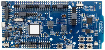
보드 정보는 nRF52840 DK 웹사이트에서 확인할 수 있습니다. nRF52840 Product Specification에는 프로세서 정보와 데이터시트가 들어 있습니다.
하드웨어
nRF52840 DK에는 외부 oscillator가 두 개 있습니다. 저속 clock은 32.768 kHz, main clock은 32 MHz입니다.
지원 기능
nrf52840dk/nrf52840 보드 구성에서 지원하는 하드웨어 기능은 다음과 같습니다.
| 인터페이스 | 컨트롤러 | 드라이버/컴포넌트 |
|---|---|---|
ADC | on-chip | adc |
CLOCK | on-chip | clock_control |
FLASH | on-chip | flash |
GPIO | on-chip | gpio |
I2C(M) | on-chip | i2c |
MPU | on-chip | arch/arm |
NVIC | on-chip | arch/arm |
PWM | on-chip | pwm |
RADIO | on-chip | Bluetooth, ieee802154 |
RTC | on-chip | system clock |
RTT | Segger | console |
SPI(M/S) | on-chip | spi |
UART | on-chip | serial |
USB | on-chip | usb |
WDT | on-chip | watchdog |
그 밖의 하드웨어 기능은 아직 이 보드에서 활성화되지 않았습니다. 전체 기능은 nRF52840 DK 웹사이트와 nRF52840 DK Hardware guide를 참고하십시오.
연결과 입출력
LED
- LED1(녹색):
P0.13 - LED2(녹색):
P0.14 - LED3(녹색):
P0.15 - LED4(녹색):
P0.16
Push button
- BUTTON1 = SW1 =
P0.11 - BUTTON2 = SW2 =
P0.12 - BUTTON3 = SW3 =
P0.24 - BUTTON4 = SW4 =
P0.25 - BOOT = SW5 = boot/reset
프로그래밍과 디버깅
nrf52840dk/nrf52840 보드용 애플리케이션은 일반적인 Zephyr 방식으로 빌드·flash·debug할 수 있습니다.
Flash
Nordic Segger 안내에 따라 필요한 소프트웨어를 설치하고 구성한 뒤 일반적인 방식으로 애플리케이션을 빌드하고 flash합니다. 다음은 hello_world 예입니다.
먼저 원하는 terminal 프로그램으로 출력을 수신합니다.
$ minicom -D <tty_device> -b 115200<tty_device>는 nRF52840 DK가 연결된 port로 바꾸십시오. Linux에서는 예를 들어 /dev/ttyACM0입니다.
# From the root of the zephyr repository
west build -b nrf52840dk/nrf52840 samples/hello_world
west flash
Debug
Segger IC를 이용한 Nordic 보드 디버깅 방법은 Nordic Segger 문서를 참고하십시오.
LED와 버튼 시험
다음 두 sample로 버튼(switch)과 LED가 Zephyr에서 올바르게 동작하는지 시험할 수 있습니다.
samples/basic/blinky
samples/basic/button
예제를 빌드하고 flash하면 보드에서 Zephyr가 정상 실행되는지 확인할 수 있습니다. 버튼과 LED 정의는 boards/nordic/nrf52840dk/nrf52840dk_nrf52840.dts에 있습니다.
UART1 핀 변경
애플리케이션에서 UART1에 다른 핀 묶음이 필요하면 애플리케이션 main directory에 다음 devicetree overlay 파일을 추가합니다.
&pinctrl {
   uart1_default_alt: uart1_default_alt {
      group1 {
         psels = <NRF_PSEL(UART_TX, 0, 14)>,
                 <NRF_PSEL(UART_RX, 0, 16)>;
      };
   };
   /* required if CONFIG_PM_DEVICE=y */
   uart1_sleep_alt: uart1_sleep_alt {
      group1 {
         psels = <NRF_PSEL(UART_TX, 0, 14)>,
                 <NRF_PSEL(UART_RX, 0, 16)>;
         low-power-enable;
      };
   };
};

&uart1 {
  pinctrl-0 = <&uart1_default_alt>;
  /* if sleep state is not used, use /delete-property/ pinctrl-1; and
   * skip the "sleep" entry.
   */
  pinctrl-1 = <&uart1_sleep_alt>;
  pinctrl-names = "default", "sleep";
};
이 overlay에서는 P0.16을 RX로, P0.14를 TX로 사용합니다.
핀 선택
핀은 보드 pinctrl 파일에서 구성할 수 있습니다. 가능한 mapping은 nRF52840 Product Specification의 7장 Hardware and Layout, 표 7.1.1 aQFN73 ball assignments에서 General purpose I/O로 표시된 핀을 확인하십시오.
nRF52840 DK에서 nRF52811 에뮬레이션
nrf52840dk/nrf52811 보드 변형은 원래 nrf52840dk/nrf52840을 수정해 nRF52840 변형인 nRF52811 IC의 제한을 강제한 대상입니다.
Nordic은 nRF52811용 개발 키트를 제공하지 않으므로 nRF52840 Development Kit(PCA10056)를 사용하면서 이 대상으로 nRF52811용 소프트웨어를 개발할 수 있습니다. 개발 보드는 앞의 nRF52840 DK 설명을, IC 자체의 공식 정보는 nRF52811 웹사이트를 참고하십시오.
Source
출처
영어 원문에는 문단, 문서 지시문, 표, 코드, 코드 심벌, 경로를 그대로 보존했습니다.