Part 1
요약·해설
VTR2 voltage, UART crisis recovery, SAF/MAF boot와 128MBit SPI image build를 다룹니다.
MEC1723/1727/1728 · Cortex-M4
Shared SPI · SAF · MAF
Standalone · MECC mated
Part 2
접을 수 있는 영어 원문 전체
영어 원문 전체 펼치기
DC4785542C77C78F490D154F12ED45541A8C8D934B1B685DC05D4FF8B4D37954
.. _mec172xmodular_6930:

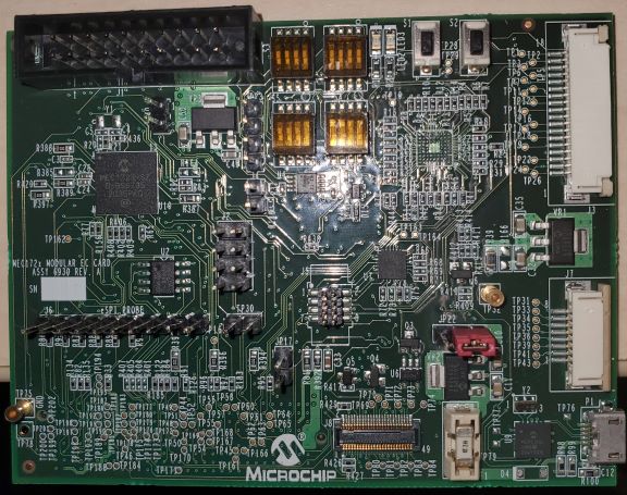
Microchip MEC172x Modular Card ASSY6930 (Rev. B)
################################################

Overview
********
The MEC172x Modular Card ASSY6930 (Rev. B) is a development board to evaluate the
Microchip MEC172X series microcontrollers.  This board can work standalone
or be mated with any platform that complies with MECC specification.


.. image:: ../../../../../../../boards/microchip/mec172xmodular_assy6930/doc/mec172xmodular_assy6930.jpg
   :width: 576px
   :align: center
   :alt: MEC172x Modular ASSY 6930


Hardware
********

- MEC172x (MEC1723, MEC1727 and MEC1728) ARM Cortex-M4 Processor
- 416 KB RAM and 128 KB boot ROM
- UART1 using microUSB
- PECI interface 3.0
- FAN, PWM and TACHO pins
- 5 SMBus instances
- eSPI header
- VCI interface
- 1 hardware driven PS/2 ports
- Keyboard interface headers

For more information about the SOC please see `MEC172x Reference Manual`_

At difference from MEC172x evaluation board, modular MEC172x exposes the pins in 2 different ways:

1) Standalone mode via headers

   - GPIOs
   - JTAG port
   - eSPI bus
   - I2C0, I2C1 and I2C6
   - PWM1, PWM2, PWM3
   - Shared  SPI
   - Keyboard Interface

2) Mated mode with another platform that has a high density MECC connector

   - FAN, PWM8
   - I2C3 and I2C7
   - eSPI bus

The board is powered through the +5V USB micro-A connector or from the MECC connector.


Supported Features
==================

The mec172xmodular_assy6930 (Rev. B) board configuration supports the following hardware features:

+-----------+------------+-------------------------------------+
| Interface | Controller | Driver/Component                    |
+===========+============+=====================================+
| NVIC      | on-chip    | nested vector interrupt controller  |
+-----------+------------+-------------------------------------+
| SYSTICK   | on-chip    | systick                             |
+-----------+------------+-------------------------------------+
| UART      | on-chip    | serial port                         |
+-----------+------------+-------------------------------------+
| GPIO      | on-chip    | gpio                                |
+-----------+------------+-------------------------------------+
| I2C       | on-chip    | i2c                                 |
+-----------+------------+-------------------------------------+
| PINMUX    | on-chip    | pinmux                              |
+-----------+------------+-------------------------------------+
| PS/2      | on-chip    | ps2                                 |
+-----------+------------+-------------------------------------+
| KSCAN     | on-chip    | kscan                               |
+-----------+------------+-------------------------------------+
| TACH      | on-chip    | tachometer                          |
+-----------+------------+-------------------------------------+
| RPMFAN    | on-chip    | Fan speed controller                |
+-----------+------------+-------------------------------------+

Other hardware features are not currently supported by Zephyr (at the moment)

The default configuration can be found in the
:zephyr_file:`boards/microchip/mec172xmodular_assy6930/mec172xmodular_assy6930_defconfig` Kconfig file.

Connections and IOs
===================

This evaluation board kit is comprised of the following HW blocks:

- MEC172x Modular ASSY 6930 Rev B1 `MEC172x Modular EC Card - Assy_6930 Rev B1p1`_

System Clock
============

The MEC172x MCU is configured to use the 96Mhz internal oscillator with the
on-chip PLL to generate a resulting EC clock rate of 12 MHz. See Processor clock
control register in chapter 4 "4.0 POWER, CLOCKS, and RESETS" of the data sheet in
the references at the end of this document.

Serial Port
===========

UART1 is configured for serial logs.

Jumper settings
***************

Please follow the jumper settings below to properly demo this
board. Advanced users may deviate from this recommendation.

Jumper setting for MEC172x Modular Assy 6930 Rev B1p1
=====================================================

Power-Related Jumpers
---------------------
If you wish to power from type A/B connector ``P1`` set the jumper ``JP22 1-2``.
This is required for standalone mode.
If you wish to power through MECC connector ``P2`` and mate to external platform,
set the jumper to ``JP22 2-3``.

NOTE: A single jumper is required in JP22.

If you wish to set VTR2 to 3.3V, set the jumper ``JP26 2-3``.
This is required for Windows application.
If you wish to set VTR2 to 1.8V, set the jumper ``JP26 1-2``.
This is required for Chrome application.

Boot-ROM Straps
---------------
This jumper configures MEC172x Boot-ROM strap.

+---------------------+
| JP23 (UART_BSTRAP)  |
+=====================+
| 1-2                 |
+---------------------+

``JP23 1-2`` pulls UART_BSTRAP to GND.  MEC172x Boot-ROM samples UART_BSTRAP and if low,
UART interface is used for Crisis Recovery.

Boot Source Select
------------------
The jumpers below configure MEC172x to boot from Shared SPI, Slave Attached Flash (SAF)
or Master Attached Flash (MAF).

+-------------------+----------+
| Boot Source       | JP25     |
+===================+==========+
| Shared SPI or SAF | 5-6      |
+-------------------+----------+
| MAF               | 1-2, 4-6 |
+-------------------+----------+


Programming and Debugging
*************************

Setup
=====

#. If you use Dediprog SF100 programmer, then setup it.

   Windows version can be found at the `SF100 Product page`_.

   Linux version source code can be found at `SF100 Linux GitHub`_.
   Follow the `SF100 Linux manual`_ to complete setup of the SF100 programmer.
   For Linux please make sure that you copied ``60-dediprog.rules``
   from the ``SF100Linux`` folder to the :code:`/etc/udev/rules.s` (or rules.d)
   then restart service using:

   .. code-block:: console

      $ udevadm control --reload

   Add directory with program ``dpcmd`` (on Linux)
   or ``dpcmd.exe`` (on Windows) to your ``PATH``.

#. Clone the `MEC172x SPI Image Gen`_ repository or download the files within
   that directory.

#. Make the image generation available for Zephyr, by making the tool
   searchable by path, for example:

   .. code-block:: console

      -DMEC172X_SPI_GEN=<path to spi_gen tool>/mec172x_spi_gen_lin_x86_64

   Note that the tools for Linux and Windows have different file names.

#. The default MEC172X_SPI_CFG file is spi_cfg.txt located in ${BOARD_DIR}/support.
   Example of SPI_CFG for 4MBit (spi_cfg_4MBit.txt) and 128MBit (spi_cfg_128MBit.txt)
   SPI flash can be found in the same folder.  If needed, a custom SPI image
   configuration file can be specified to override the default one.

   .. code-block:: console

      -DMEC172X_SPI_CFG=<path to spi_cfg file>/spi_cfg.txt

#. Example command to generate 128MBit spi image for hello_world:

   .. code-block:: console

      west build -p auto -b mec172xmodular_assy6930 samples/hello_world -- -DMEC172X_SPI_GEN=$HOME/CPGZephyrDocs/MEC172x/SPI_image_gen/mec172x_spi_gen_lin_x86_64 -DMEC172X_SPI_CFG=$HOME/zephyrproject/zephyr/boards/microchip/mec172xmodular_assy6930/support/spi_cfg_128MBit.txt


Wiring
========

#. Connect programmer to the header J2 on the ASSY6930 board, it will flash the SPI NOR chip
   ``U2``. Make sure that your programmer's offset is 0x0.
   For programming you can use Dediprog SF100 or a similar tool for flashing SPI chips.

   +------------+---------------+
   |  Dediprog  |               |
   |  Connector |      J2       |
   +============+===============+
   |    VCC     |       1       |
   +------------+---------------+
   |    GND     |       2       |
   +------------+---------------+
   |    CS      |       3       |
   +------------+---------------+
   |    CLK     |       4       |
   +------------+---------------+
   |    MISO    |       6       |
   +------------+---------------+
   |    MOSI    |       5       |
   +------------+---------------+

#. Connect UART1 port of the mec172xmodular_assy6930 (Rev. B) board
   to your host computer using the RS232 cable.

#. Apply power to the board via a micro-USB cable.
   Configure this option by using a jumper between ``JP22 1-2``.

Building
========

#. Build :ref:`hello_world` application as you would normally do.

#. The file :file:`spi_image.bin` will be created if the build system
   can find the image generation tool. This binary image can be used
   to flash the SPI chip.

Flashing
========

#. Run your favorite terminal program to listen for output.
   Under Linux the terminal should be :code:`/dev/ttyUSB0`. Do not close it.

   For example:

   .. code-block:: console

      $ minicom -D /dev/ttyUSB0 -o

   The -o option tells minicom not to send the modem initialization
   string. Connection should be configured as follows:

   - Speed: 115200
   - Data: 8 bits
   - Parity: None
   - Stop bits: 1

#. Flash your board using ``west`` from the second terminal window.
   Split first and second terminal windows to view both of them.

   .. code-block:: console

      $ west flash

   .. note:: When west process started press Reset button ``S1`` and do not release it
    till the whole west process will not be finished successfully.

#. You should see ``"Hello World! mec172xmodular_assy6930"`` in the first terminal window.
   If you don't see this message, press the Reset button and the message should appear.

Debugging
=========
``J1`` header on the board allows for JTAG connections for debug.

Troubleshooting
===============
#. In case you don't see your application running, please make sure ``LED1`` is lit.
   If ``LED1`` is off, check the power-related jumpers again.

#. If you can't program the board using Dediprog, disconnect and reconnect cable connected to
   ``P1`` and try again.

#. If Dediprog can't detect the onboard flash, press the board's ``S1`` Reset button and try again.


References
**********
.. target-notes::

.. _MEC172x Reference Manual:
    https://github.com/MicrochipTech/CPGZephyrDocs/blob/master/MEC172x/MEC172x-Data-Sheet.pdf
.. _MEC172x Modular EC Card - Assy_6930 Rev B1p1:
    https://github.com/MicrochipTech/CPGZephyrDocs/blob/master/MEC172x/MEC172X-MECC_Assy_6930_B1p1-SCH.pdf
.. _MEC172x SPI Image Gen:
    https://github.com/MicrochipTech/CPGZephyrDocs/tree/master/MEC172x/SPI_image_gen
.. _SF100 Linux GitHub:
    https://github.com/DediProgSW/SF100Linux
.. _SF100 Product page:
    https://www.dediprog.com/product/SF100
.. _SF100 Linux manual:
    https://www.dediprog.com/download/save/727.pdf
Part 3
한국어 전문 번역
개요
MEC172x Modular Card ASSY6930 Rev B는 MEC172X series 평가용 development board이며 standalone 또는 MECC platform에 결합해 사용할 수 있습니다.
Hardware
- MEC1723·1727·1728 Arm Cortex-M4
- 416KB RAM, 128KB boot ROM
- microUSB UART1, PECI 3.0
- FAN·PWM·TACHO, SMBus 5개, eSPI, VCI
- Hardware-driven PS/2 1개와 keyboard header
Standalone header는 GPIO, JTAG, eSPI, I2C0·1·6, PWM1·2·3, Shared SPI와 keyboard interface를 제공합니다. MECC mated mode는 FAN·PWM8, I2C3·7과 eSPI를 제공합니다. +5V USB micro-A 또는 MECC에서 전원을 공급합니다.
지원 기능
| Interface | Controller | Driver/Component |
|---|---|---|
| NVIC | on-chip | nested vector interrupt controller |
| SYSTICK | on-chip | systick |
| UART | on-chip | serial port |
| GPIO | on-chip | gpio |
| I2C | on-chip | i2c |
| PINMUX | on-chip | pinmux |
| PS/2 | on-chip | ps2 |
| KSCAN | on-chip | kscan |
| TACH | on-chip | tachometer |
| RPMFAN | on-chip | Fan speed controller |
Default configuration은 boards/microchip/mec172xmodular_assy6930/mec172xmodular_assy6930_defconfig입니다.
연결과 I/O
MEC172x Modular ASSY6930 Rev B1은 96MHz oscillator와 PLL로 EC clock 12MHz를 생성하며 UART1이 serial log를 담당합니다.
Jumper 설정
Power
Standalone USB P1 사용 시 JP22 1-2, MECC P2 사용 시 JP22 2-3입니다. JP22에는 jumper 하나만 둡니다. Windows application용 VTR2 3.3V는 JP26 2-3, Chrome application용 1.8V는 JP26 1-2입니다.
Boot-ROM strap
| JP23 UART_BSTRAP |
|---|
| 1-2 |
JP23 1-2는 UART_BSTRAP을 GND로 당기며 Boot-ROM이 low를 읽으면 Crisis Recovery에 UART를 사용합니다.
Boot source
| Boot Source | JP25 |
|---|---|
| Shared SPI or SAF | 5-6 |
| MAF | 1-2, 4-6 |
Programming과 Debugging
Setup
Dediprog SF100 programmer를 사용한다면 먼저 설정합니다. Windows version은 SF100 Product page에서, Linux source는 SF100 Linux GitHub에서 구할 수 있습니다. Linux에서는 manual에 따라 60-dediprog.rules를 /etc/udev/rules.s 또는 rules.d로 복사하고 다음 명령으로 service를 reload합니다.
$ udevadm control --reloadLinux의 dpcmd 또는 Windows의 dpcmd.exe가 있는 directory를 PATH에 추가합니다.
MEC172x SPI Image Gen을 clone하고 다음 CMake option으로 tool을 지정합니다.
-DMEC172X_SPI_GEN=<path to spi_gen tool>/mec172x_spi_gen_lin_x86_64Default config는 ${BOARD_DIR}/support/spi_cfg.txt이며 4MBit·128MBit example도 같은 folder에 있습니다. 필요하면 custom config를 지정합니다.
-DMEC172X_SPI_CFG=<path to spi_cfg file>/spi_cfg.txt128MBit hello_world image 생성 예입니다.
west build -p auto -b mec172xmodular_assy6930 samples/hello_world -- -DMEC172X_SPI_GEN=$HOME/CPGZephyrDocs/MEC172x/SPI_image_gen/mec172x_spi_gen_lin_x86_64 -DMEC172X_SPI_CFG=$HOME/zephyrproject/zephyr/boards/microchip/mec172xmodular_assy6930/support/spi_cfg_128MBit.txtWiring
Programmer를 ASSY6930의 J2에 연결해 SPI NOR U2 offset 0x0을 flash합니다.
| Dediprog Connector | Board connector pin |
|---|---|
| VCC | 1 |
| GND | 2 |
| CS | 3 |
| CLK | 4 |
| MISO | 6 |
| MOSI | 5 |
UART1을 RS232로 host에 연결하고 JP22 1-2 상태에서 micro-USB 전원을 인가합니다.
Building
Tool을 찾으면 build system이 spi_image.bin을 생성합니다.
Flashing
첫 terminal은 닫지 말고 다음처럼 엽니다.
$ minicom -D /dev/ttyUSB0 -o- Speed: 115200
- Data: 8 bits
- Parity: None
- Stop bits: 1
두 번째 terminal에서 flash합니다.
$ west flashWest가 실행되면 Reset S1을 누르고 성공적으로 끝날 때까지 놓지 않습니다. 첫 terminal에 Hello World! mec172xmodular_assy6930가 나타나야 합니다.
Debugging
J1 header가 JTAG debug connection을 제공합니다.
Troubleshooting
LED1이 꺼졌으면 power jumper를 확인합니다.- Dediprog programming 실패 시
P1cable을 다시 연결합니다. - On-board flash 감지 실패 시
S1Reset을 누릅니다.
참고 자료
Source
출처
영어 원문에는 문단, 문서 지시문, 표, 코드, 코드 심벌, 경로를 그대로 보존했습니다.