Part 1
요약·해설
MEC1501/MEC152x image 비호환, UART2·SHD SPI routing과 SF100 wiring을 다룹니다.
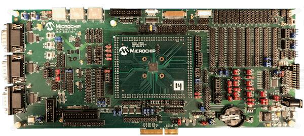
MEC1521 · Cortex-M4
ASSY6853 · ASSY6883 · ASSY6791
SPI Image Gen · SF100 · west flash
Part 2
접을 수 있는 영어 원문 전체
영어 원문 전체 펼치기
5F1FDF4C1C746D58CDB9CB180C93D8B1E6B84BCB048ADA23622A18C98A097987
.. _mec15xxevb_assy6853:

Microchip MEC15xxEVB ASSY6853
#############################

Overview
********

The MEC15xxEVB_ASSY6853 kit is a future development platform to evaluate the
Microchip MEC15XX series microcontrollers. This board needs to be mated with
part number MEC1501 144WFBA SOLDER DC ASSY 6860(cpu board) in order to operate.
The MEC152x has superseded the MEC1501 in production. MEC152x is identical to
MEC150x except for an enhanced Boot-ROM SPI loader. The SPI image format has
been updated requiring a new SPI image tool. MEC1501 and MEC152x SPI image
formats are not compatible with each other. Evaluation and cpu boards are
compatible.

.. image:: ../../../../../../../boards/microchip/mec15xxevb_assy6853/doc/mec15xxevb_assy6853.jpg
     :align: center
     :alt: MEC15XX EVB ASSY 6853

Hardware
********

- MEC1521HA0SZ ARM Cortex-M4 Processor
- 256 KB RAM and 64 KB boot ROM
- Keyboard interface
- ADC & GPIO headers
- UART0, UART1, and UART2
- FAN0, FAN1, FAN2 headers
- FAN PWM interface
- JTAG/SWD, ETM and MCHP Trace ports
- PECI interface 3.0
- I2C voltage translator
- 10 SMBUS headers
- 4 SGPIO headers
- VCI interface
- 5 independent Hardware Driven PS/2 Ports
- eSPI header
- 3 Breathing/Blinking LEDs
- 2 Sockets for SPI NOR chips
- One reset and VCC_PWRDGD pushbuttons
- One external PCA9555 I/O port with jumper selectable I2C address.
- One external LTC2489 delta-sigma ADC with jumper selectable I2C address.
- Board power jumper selectable from +5V 2.1mm/5.5mm barrel connector or USB Micro A connector.

For more information about the SOC's please see `MEC152x Reference Manual`_

Supported Features
==================

The mec15xxevb_assy6853 board configuration supports the following hardware
features:

+-----------+------------+-------------------------------------+
| Interface | Controller | Driver/Component                    |
+===========+============+=====================================+
| NVIC      | on-chip    | nested vector interrupt controller  |
+-----------+------------+-------------------------------------+
| SYSTICK   | on-chip    | systick                             |
+-----------+------------+-------------------------------------+
| UART      | on-chip    | serial port                         |
+-----------+------------+-------------------------------------+
| GPIO      | on-chip    | gpio                                |
+-----------+------------+-------------------------------------+
| I2C       | on-chip    | i2c                                 |
+-----------+------------+-------------------------------------+
| PINMUX    | on-chip    | pinmux                              |
+-----------+------------+-------------------------------------+
| PS/2      | on-chip    | ps2                                 |
+-----------+------------+-------------------------------------+
| KSCAN     | on-chip    | kscan                               |
+-----------+------------+-------------------------------------+
| TACH      | on-chip    | tachometer                          |
+-----------+------------+-------------------------------------+


Other hardware features are not currently supported by Zephyr (at the moment)

The default configuration can be found in the
:zephyr_file:`boards/microchip/mec15xxevb_assy6853/mec15xxevb_assy6853_defconfig` Kconfig file.

Connections and IOs
===================

This evaluation board kit is comprised of the following HW blocks:

- MEC15xx EVB ASSY 6853 Rev A `MEC15xx EVB Schematic`_
- MEC1501 144WFBA SOLDER DC ASSY 6883 with MEC152x silicon `MEC1501 Daughter Card Schematic`_
- SPI DONGLE ASSY 6791 `SPI Dongle Schematic`_

System Clock
============

The MEC1521 MCU is configured to use the 48Mhz internal oscillator with the
on-chip PLL to generate a resulting EC clock rate of 12 MHz. See Processor clock
control register in chapter 4 "4.0 POWER, CLOCKS, and RESETS" of the data sheet in
the references at the end of this document.

Serial Port
===========

UART2 is configured for serial logs.

Jumper settings
***************

Please follow the jumper settings below to properly demo this
board. Advanced users may deviate from this recommendation.

Jumper setting for MEC15xx EVB Assy 6853 Rev A1p0
=================================================

Power-related jumpers
---------------------

If you wish to power from +5V power brick, then connect to barrel connector ``P11``
(5.5mm OD, 2.1mm ID) and move the jumper to ``JP88 5-6``.

If you wish to power from micro-USB type A/B connector ``P12``, move the
jumper to ``JP88 7-8``.


.. note:: A single jumper is required in JP88.

+-------+------+------+------+------+------+------+------+------+------+------+
| JP22  | JP32 | JP33 | JP37 | JP43 | JP47 | JP54 | JP56 | JP58 | JP64 | JP65 |
+=======+======+======+======+======+======+======+======+======+======+======+
| 1-2   | 1-2  | 1-2  | 1-2  |  1-2 | 1-2  | 1-2  | 1-2  | 1-2  | 1-2  | 1-2  |
+-------+------+------+------+------+------+------+------+------+------+------+

+------+------+------+------+------+------+------+------+------+------+
| JP72 | JP73 | JP76 | JP79 | JP80 | JP81 | JP82 | JP84 | JP87 | JP89 |
+======+======+======+======+======+======+======+======+======+======+
| 1-2  | 1-2  | 1-2  | 1-2  | 1-2  | 1-2  | 1-2  | 1-2  | 1-2  | 1-2  |
+------+------+------+------+------+------+------+------+------+------+

+------+------+-------+-------+-------+
| JP90 | JP91 | JP100 | JP101 | JP118 |
+======+======+=======+=======+=======+
| 1-2  | 1-2  | 1-2   | 1-2   | 2-3   |
+------+------+-------+-------+-------+

These jumpers configure VCC Power good, nRESETI and JTAG_STRAP respectively.

+------------------+-----------+--------------+
| JP5              | JP4       | JP45         |
| (VCC Power good) | (nRESETI) | (JTAG_STRAP) |
+==================+===========+==============+
| 1-2              | 1-2       | 2-3          |
+------------------+-----------+--------------+

Boot-ROM Straps.
----------------

These jumpers configure MEC1501 Boot-ROM straps.

+-------------+------------+--------------+-------------+
| JP93        | JP11       | JP46         | JP96        |
| (CMP_STRAP) | (CR_STRAP) | (VTR2_STRAP) | (BSS_STRAP) |
+=============+============+==============+=============+
| 2-3         | 1-2        | 2-3          | 1-2         |
+-------------+------------+--------------+-------------+

``JP96 1-2`` pulls SHD SPI CS0# up to VTR2. MEC1501 Boot-ROM samples
SHD SPI CS0# and if high, it loads code from SHD SPI.

Peripheral Routing Jumpers
--------------------------

Each column of the following table illustrates how to enable UART2, SWD,
PVT SPI, SHD SPI and LED0-2 respectively.

+----------+----------+--------+-----------+----------+---------+
|  JP48    |  JP9     | JP9    | JP38      | JP98     | JP41    |
|  (UART2) |  (UART2) | (SWD)  | (PVT SPI) | (SHD SPI)| (LED0-2)|
+==========+==========+========+===========+==========+=========+
|  1-2     |          | 2-3    | 2-3       | 2-3      | 1-2     |
+----------+----------+--------+-----------+----------+---------+
|  4-5     |  4-5     |        | 5-6       | 5-6      | 3-4     |
+----------+----------+--------+-----------+----------+---------+
|  7-8     |          | 8-9    | 8-9       | 8-9      | 5-6     |
+----------+----------+--------+-----------+----------+---------+
|  10-11   |  10-11   |        | 11-12     | 11-12    |         |
+----------+----------+--------+-----------+----------+---------+
|          |          |        | 14-15     | 14-15    |         |
+----------+----------+--------+-----------+----------+---------+
|          |          |        | 17-18     | 20-21    |         |
+----------+----------+--------+-----------+----------+---------+

.. note:: For UART2 make sure JP39 have jumpers connected 1-2, 3-4.

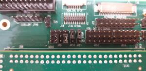
To receive UART2 serial output, please refer to the picture below
to make sure that JP9 configured for UART2 output.

.. image:: ../../../../../../../boards/microchip/mec15xxevb_assy6853/doc/mec15xxevb_assy6853_jp9_1.jpg
     :align: center
     :alt: JP9 header Assy6853

Jumper settings for MEC1501 144WFBGA Socket DC Assy 6883 Rev B1p0
=================================================================

The jumper configuration explained above covers the base board. The ASSY
6883 MEC1501 CPU board provides capability for an optional, external 32KHz
clock source. The card includes a 32KHz crystal oscillator. The card can
also be configured to use an external 50% duty cycle 32KHz source on the
XTAL2/32KHZ_IN pin. Note, firmware must set the MEC15xx clock enable
register to select the external source matching the jumper settings. If
using the MEC15xx internal silicon oscillator then the 32K jumper settings
are don't cares. ``JP1`` is for scoping test clock outputs. Please refer to
the schematic in reference section below.

Parallel 32KHz crystal configuration
------------------------------------
+-------+-------+
| JP2   | JP3   |
+=======+=======+
| 1-2   | 2-3   |
+-------+-------+

External 32KHz 50% duty cycle configuration
-------------------------------------------
+-------+-------+
| JP2   | JP3   |
+=======+=======+
| NC    | 1-2   |
+-------+-------+


Jumper settings for MEC1503 144WFBGA Socket DC Assy 6856 Rev B1p0
=================================================================

The MEC1503 ASSY 6856 CPU card does not include an onboard external
32K crystal or oscillator. The one jumper block ``JP1`` is for scoping
test clock outputs not for configuration. Please refer to schematic
in reference section below.

Programming and Debugging
*************************

Setup
=====
#. If you use Dediprog SF100 programmer, then setup it.

   Windows version can be found at the `SF100 Product page`_.

   Linux version source code can be found at `SF100 Linux GitHub`_.
   Follow the `SF100 Linux manual`_ to complete setup of the SF100 programmer.
   For Linux please make sure that you copied ``60-dediprog.rules``
   from the ``SF100Linux`` folder to the :code:`/etc/udev/rules.s` (or rules.d)
   then restart service using:

   .. code-block:: console

      $ udevadm control --reload

   Add directory with program ``dpcmd`` (on Linux)
   or ``dpcmd.exe`` (on Windows) to your ``PATH``.

#. Clone the `MEC152x SPI Image Gen`_ repository or download the files within
   that directory. For the pre-production MEC150x use `MEC150x SPI Image Gen`_
   repository.

#. Make the image generation available for Zephyr, by making the tool
   searchable by path, or by setting an environment variable
   ``EVERGLADES_SPI_GEN``, for example:

   .. code-block:: console

      export EVERGLADES_SPI_GEN=<path to tool>/everglades_spi_gen_RomE

   Note that the tools for Linux and Windows have different file names.
   For the pre-production MEC1501 SOC use everglades_spi_gen_lin64.

#. If needed, a custom SPI image configuration file can be specified
   to override the default one.

   .. code-block:: console

      export EVERGLADES_SPI_CFG=custom_spi_cfg.txt

Wiring
========
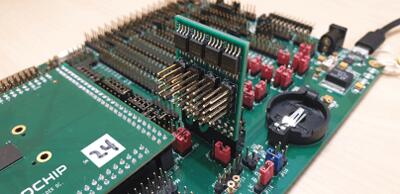
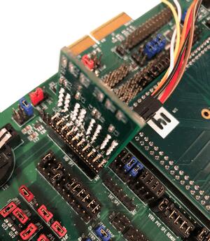
#. Connect the SPI Dongle ASSY 6791 to ``J44`` in the EVB.

   .. image:: ../../../../../../../boards/microchip/mec15xxevb_assy6853/doc/spidongle_assy6791_view1.jpg
        :align: center
        :alt: SPI DONGLE ASSY 6791 Connected

#. Connect programmer to the header J6 on the Assy6791 board, it will flash the SPI NOR chip ``U3``
   Make sure that your programmer's offset is 0x0.
   For programming you can use Dediprog SF100 or a similar tool for flashing SPI chips.

   .. list-table:: Microchip board wiring
      :align: center

      * -
          .. image:: ../../../../../../../boards/microchip/mec15xxevb_assy6853/doc/spidongle_assy6791.jpg
             :align: center
             :alt: SPI DONGLE ASSY 6791

        -
          .. image:: ../../../../../../../boards/microchip/mec15xxevb_assy6853/doc/spidongle_assy6791_view2.jpg
             :align: center
             :alt: SPI DONGLE ASSY 6791 view 2

          |

          .. image:: ../../../../../../../boards/microchip/mec15xxevb_assy6853/doc/dediprog_connector_2.jpg
             :align: center
             :alt: SPI DONGLE ASSY 6791 Connected


   .. note:: Remember that SPI MISO/MOSI are swapped on Dediprog headers!
    Use separate wires to connect Dediprog pins with pins on the Assy6791 SPI board.
    Wiring connection is described in the table below.

    +------------+---------------+
    |  Dediprog  |  Assy6791     |
    |  Connector |  J6 Connector |
    +============+===============+
    |    VCC     |       1       |
    +------------+---------------+
    |    GND     |       2       |
    +------------+---------------+
    |    CS      |       3       |
    +------------+---------------+
    |    CLK     |       4       |
    +------------+---------------+
    |    MISO    |       6       |
    +------------+---------------+
    |    MOSI    |       5       |
    +------------+---------------+

#. Connect UART2 port of the MEC15xxEVB_ASSY_6853 board
   to your host computer using the RS232 cable.

#. Apply power to the board via a micro-USB cable.
   Configure this option by using a jumper between ``JP88 7-8``.

   .. image:: ../../../../../../../boards/microchip/mec15xxevb_assy6853/doc/jp88_power_options.jpg
        :align: center
        :alt: SPI DONGLE ASSY 6791 Connected

#. Final wiring for the board should look like this:

   .. image:: ../../../../../../../boards/microchip/mec15xxevb_assy6853/doc/mec_board_setup.jpg
        :align: center
        :alt: SPI DONGLE ASSY 6791 Connected

Building
========
#. Build :ref:`hello_world` application as you would normally do.

#. The file :file:`spi_image.bin` will be created if the build system
   can find the image generation tool. This binary image can be used
   to flash the SPI chip.

Flashing
========
#. Run your favorite terminal program to listen for output.
   Under Linux the terminal should be :code:`/dev/ttyUSB0`. Do not close it.

   For example:

   .. code-block:: console

      $ minicom -D /dev/ttyUSB0 -o

   The -o option tells minicom not to send the modem initialization
   string. Connection should be configured as follows:

   - Speed: 115200
   - Data: 8 bits
   - Parity: None
   - Stop bits: 1

#. Flash your board using ``west`` from the second terminal window.
   Split first and second terminal windows to view both of them.

   .. code-block:: console

      $ west flash

   .. note:: When west process started press Reset button and do not release it
    till the whole west process will not be finished successfully.

    .. image:: ../../../../../../../boards/microchip/mec15xxevb_assy6853/doc/reset_button_1.jpg
         :align: center
         :alt: SPI DONGLE ASSY 6791 Connected


   .. note:: If you don't want to press Reset button every time, you can disconnect
    SPI Dongle ASSY 6791 from the EVB during the west flash programming.
    Then connect it back to the ``J44`` header and apply power to the EVB.
    Result will be the same.


#. You should see ``"Hello World! mec15xxevb_assy6853"`` in the first terminal window.
   If you don't see this message, press the Reset button and the message should appear.

Debugging
=========
This board comes with a Cortex ETM port which facilitates tracing and debugging
using a single physical connection.  In addition, it comes with sockets for
JTAG only sessions.

Troubleshooting
===============
#. In case you don't see your application running, please make sure ``LED7``, ``LED8``, and ``LED1``
   are lit. If one of these is off, then check the power-related jumpers again.

#. If you can't program the board using Dediprog, disconnect the Assy6791
   from the main board Assy6853 and try again.

#. If Dediprog can't detect the onboard flash, press the board's Reset button and try again.

Notes
=====
#. To enable PCA9555PW and test the I2C on mec15xxevb_assy6853, additional works are needed:

   As the I2C slave device NXP pca95xx on mec15xxevb_assy6853 is connected to I2C00 port,
   however, I2C00 port is shared with UART2 RS232 to TTL converter used to catch serial log,
   so it's not possible to use UART2 and I2C00 port simultaneously. We need to change to use
   I2C01 port by making some jumpers setting as below:

 * JP99         1-2     Connected       Connect I2C01_SDA from CPU to header J5
 * JP99         13-14   Connected       Connect I2C01_SCL from CPU to header J5
 * JP25         21-22   Connected       External pull-up for I2C01_SDA
 * JP25         23-24   Connected       External pull-up for I2C01_SCL
 *
 * JP44.1       J5.1    Connected       Connect NXP PCA95xx to I2C01
 * JP44.3       J5.3    Connected       Connect NXP PCA95xx to I2C01


References
**********
.. target-notes::

.. _MEC1501 Preliminary Data Sheet:
    https://github.com/MicrochipTech/CPGZephyrDocs/blob/master/MEC1501/MEC1501_Datasheet.pdf
.. _MEC1501 Reference Manual:
    https://github.com/MicrochipTech/CPGZephyrDocs/blob/master/MEC1501/MEC1501_Datasheet.pdf
.. _MEC152x Preliminary Data Sheet:
    https://github.com/MicrochipTech/CPGZephyrDocs/blob/master/MEC152x/MEC152x_Datasheet.pdf
.. _MEC152x Reference Manual:
    https://github.com/MicrochipTech/CPGZephyrDocs/blob/master/MEC152x/MEC152x_Datasheet.pdf
.. _MEC15xx EVB Schematic:
    https://github.com/MicrochipTech/CPGZephyrDocs/blob/master/MEC1501/Everglades%20EVB%20-%20Assy_6853%20Rev%20A1p1%20-%20SCH.pdf
.. _MEC1501 Daughter Card Schematic:
    https://github.com/MicrochipTech/CPGZephyrDocs/blob/master/MEC1501/MEC1501%20Socket%20DC%20for%20EVERGLADES%20EVB%20-%20Assy_6883%20Rev%20A0p1%20-%20SCH.pdf
.. _MEC1503 Daughter Card Schematic:
    https://github.com/MicrochipTech/CPGZephyrDocs/blob/master/MEC1501/MEC1503%20Socket%20DC%20for%20EVERGLADES%20EVB%20-%20Assy_6856%20Rev%20A1p0%20-%20SCH.pdf
.. _SPI Dongle Schematic:
    https://github.com/MicrochipTech/CPGZephyrDocs/blob/master/MEC1501/SPI%20Dongles%20and%20Aardvark%20Interposer%20Assy%206791%20Rev%20A1p1%20-%20SCH.pdf
.. _MEC152x SPI Image Gen:
    https://github.com/MicrochipTech/CPGZephyrDocs/tree/master/MEC152x/SPI_image_gen
.. _MEC150x SPI Image Gen:
    https://github.com/MicrochipTech/CPGZephyrDocs/tree/master/MEC1501/SPI_image_gen
.. _SF100 Linux GitHub:
    https://github.com/DediProgSW/SF100Linux
.. _SF100 Product page:
    https://www.dediprog.com/product/SF100
.. _SF100 Linux manual:
    https://www.dediprog.com/download/save/727.pdf
Part 3
한국어 전문 번역
개요
MEC15xxEVB ASSY6853 kit는 Microchip MEC15XX series microcontroller 평가용 platform이며 동작하려면 MEC1501 144WFBGA SOLDER DC ASSY6860 CPU board와 결합해야 합니다. Production에서는 MEC152x가 MEC1501을 대체했습니다. MEC152x는 enhanced Boot-ROM SPI loader를 제외하면 MEC150x와 같지만 SPI image format과 생성 tool이 바뀌어 두 image format은 호환되지 않습니다. Evaluation board와 CPU board 자체는 호환됩니다.
Hardware
- MEC1521HA0SZ Arm Cortex-M4, 256KB RAM, 64KB boot ROM
- Keyboard, ADC·GPIO header, UART0·1·2
- FAN0·1·2와 FAN PWM, JTAG/SWD·ETM·MCHP Trace
- PECI 3.0, I2C voltage translator, SMBUS 10개, SGPIO 4개, VCI
- Hardware-driven PS/2 port 5개, eSPI, breathing/blinking LED 3개
- SPI NOR socket 2개, reset·VCC_PWRDGD button
- PCA9555 I/O와 LTC2489 delta-sigma ADC, 선택 가능한 I2C address
- Barrel connector 또는 USB Micro-A를 선택하는 power jumper
지원 기능
| Interface | Controller | Driver/Component |
|---|---|---|
| NVIC | on-chip | nested vector interrupt controller |
| SYSTICK | on-chip | systick |
| UART | on-chip | serial port |
| GPIO | on-chip | gpio |
| I2C | on-chip | i2c |
| PINMUX | on-chip | pinmux |
| PS/2 | on-chip | ps2 |
| KSCAN | on-chip | kscan |
| TACH | on-chip | tachometer |
Default configuration은 boards/microchip/mec15xxevb_assy6853/mec15xxevb_assy6853_defconfig입니다.
연결과 I/O
Kit는 MEC15xx EVB ASSY6853, MEC152x silicon을 담은 ASSY6883 daughter card와 SPI Dongle ASSY6791로 구성됩니다. MEC1521은 48MHz oscillator와 PLL로 EC clock 12MHz를 만들며 UART2가 serial log를 담당합니다.
Jumper 설정
Power-related jumpers
+5V barrel P11 사용 시 JP88 5-6, micro-USB P12 사용 시 JP88 7-8로 둡니다. JP88에는 jumper 하나만 둡니다.
| JP22 | JP32 | JP33 | JP37 | JP43 | JP47 | JP54 | JP56 | JP58 | JP64 | JP65 |
|---|---|---|---|---|---|---|---|---|---|---|
| 1-2 | 1-2 | 1-2 | 1-2 | 1-2 | 1-2 | 1-2 | 1-2 | 1-2 | 1-2 | 1-2 |
| JP72 | JP73 | JP76 | JP79 | JP80 | JP81 | JP82 | JP84 | JP87 | JP89 |
|---|---|---|---|---|---|---|---|---|---|
| 1-2 | 1-2 | 1-2 | 1-2 | 1-2 | 1-2 | 1-2 | 1-2 | 1-2 | 1-2 |
| JP90 | JP91 | JP100 | JP101 | JP118 |
|---|---|---|---|---|
| 1-2 | 1-2 | 1-2 | 1-2 | 2-3 |
VCC power-good, nRESETI와 JTAG_STRAP 설정입니다.
| JP5 VCC Power good | JP4 nRESETI | JP45 JTAG_STRAP |
|---|---|---|
| 1-2 | 1-2 | 2-3 |
Boot-ROM straps
| JP93 CMP_STRAP | JP11 CR_STRAP | JP46 VTR2_STRAP | JP96 BSS_STRAP |
|---|---|---|---|
| 2-3 | 1-2 | 2-3 | 1-2 |
JP96 1-2는 SHD SPI CS0#을 VTR2로 pull-up하며 high이면 Boot-ROM이 SHD SPI에서 code를 load합니다.
Peripheral routing
각 열은 UART2, SWD, PVT SPI, SHD SPI와 LED0-2를 활성화하는 setting입니다.
| Row | JP48 UART2 | JP9 UART2 | JP9 SWD | JP38 PVT SPI | JP98 SHD SPI | JP41 LED0-2 |
|---|---|---|---|---|---|---|
| 1 | 1-2 | 2-3 | 2-3 | 2-3 | 1-2 | |
| 2 | 4-5 | 4-5 | 5-6 | 5-6 | 3-4 | |
| 3 | 7-8 | 8-9 | 8-9 | 8-9 | 5-6 | |
| 4 | 10-11 | 10-11 | 11-12 | 11-12 | ||
| 5 | 14-15 | 14-15 | ||||
| 6 | 17-18 | 20-21 |
UART2에는 JP39 1-2, 3-4도 필요하며 JP9가 UART2 output으로 구성됐는지 확인합니다.
ASSY6883 optional 32KHz source
ASSY6883 CPU board는 parallel 32KHz crystal 또는 XTAL2/32KHZ_IN의 external 50% duty-cycle source를 선택할 수 있습니다. Firmware clock-enable register도 jumper와 일치해야 하며 internal oscillator 사용 시 이 jumper는 don't-care입니다. JP1은 test clock output 측정용입니다.
| JP2 | JP3 |
|---|---|
| 1-2 | 2-3 |
| JP2 | JP3 |
|---|---|
| NC | 1-2 |
ASSY6856
MEC1503 ASSY6856 CPU card에는 external 32K crystal/oscillator가 없으며 JP1은 test clock output 측정용일 뿐 configuration용이 아닙니다.
Programming과 Debugging
Setup
Dediprog SF100 programmer를 사용한다면 먼저 설정합니다. Windows version은 SF100 Product page에서, Linux source는 SF100 Linux GitHub에서 구할 수 있습니다. Linux에서는 manual에 따라 60-dediprog.rules를 /etc/udev/rules.s 또는 rules.d로 복사하고 다음 명령으로 service를 reload합니다.
$ udevadm control --reloadLinux의 dpcmd 또는 Windows의 dpcmd.exe가 있는 directory를 PATH에 추가합니다.
MEC152x SPI Image Gen을 clone합니다. Pre-production MEC150x는 MEC150x SPI Image Gen을 사용합니다. Tool을 PATH에 두거나 환경 변수를 설정합니다.
export EVERGLADES_SPI_GEN=<path to tool>/everglades_spi_gen_RomELinux와 Windows filename은 다르며 pre-production MEC1501은 everglades_spi_gen_lin64를 사용합니다. 필요하면 custom configuration을 지정합니다.
export EVERGLADES_SPI_CFG=custom_spi_cfg.txtWiring
- SPI Dongle ASSY6791을 EVB의
J44에 연결합니다. - Programmer를 Assy6791의
J6에 연결해 SPI NORU3offset0x0을 flash합니다.
| SPI Dongle | Connector views |
|---|---|
 | 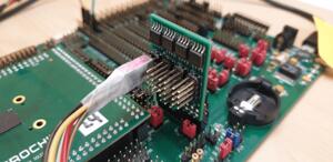 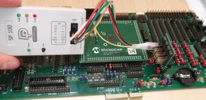 |
| Dediprog Connector | Board connector pin |
|---|---|
| VCC | 1 |
| GND | 2 |
| CS | 3 |
| CLK | 4 |
| MISO | 6 |
| MOSI | 5 |
UART2를 RS232로 host에 연결하고 JP88 7-8 상태에서 micro-USB 전원을 인가합니다.
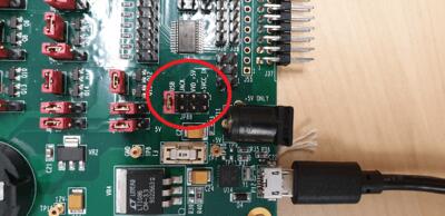
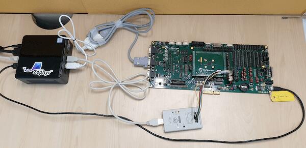
Building
hello_world를 build합니다. Image generation tool을 찾으면 spi_image.bin이 생성되며 SPI chip에 flash할 수 있습니다.
Flashing
첫 terminal에서 다음 명령으로 output을 기다립니다.
$ minicom -D /dev/ttyUSB0 -o- Speed: 115200
- Data: 8 bits
- Parity: None
- Stop bits: 1
두 번째 terminal에서 flash합니다.
$ west flashWest가 실행되는 동안 Reset button을 누르고 성공적으로 끝날 때까지 놓지 않습니다.
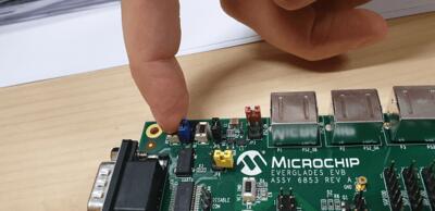
매번 Reset을 누르기 싫다면 west flash 중 SPI Dongle ASSY6791을 분리하고 완료 뒤 J44에 다시 연결해 전원을 인가할 수 있습니다. 첫 terminal에 Hello World! mec15xxevb_assy6853가 나타나야 합니다.
Debugging
Cortex ETM port와 JTAG-only socket을 제공합니다.
Troubleshooting
LED7,LED8,LED1이 켜졌는지 확인합니다.- Dediprog programming이 안 되면 Assy6791을 Assy6853에서 분리해 다시 시도합니다.
- Flash가 감지되지 않으면 Reset button을 누릅니다.
PCA9555PW와 I2C
PCA95xx가 I2C00에 연결되어 있지만 I2C00은 serial log용 UART2 converter와 공유되므로 동시에 사용할 수 없습니다. I2C01로 변경하려면 다음을 연결합니다.
JP99 1-2: I2C01_SDA CPU→J5JP99 13-14: I2C01_SCL CPU→J5JP25 21-22: I2C01_SDA pull-upJP25 23-24: I2C01_SCL pull-upJP44.1-J5.1,JP44.3-J5.3: PCA95xx→I2C01
참고 자료
원문의 MEC1501·MEC152x datasheet, EVB·daughter card·SPI dongle schematic, SPI image generator와 SF100 자료 링크는 접을 수 있는 영어 원문에 그대로 보존되어 있습니다.
Source
출처
영어 원문에는 문단, 문서 지시문, 표, 코드, 코드 심벌, 경로를 그대로 보존했습니다.