Part 1
요약·해설
ESP32-S3의 digital·analog interface, low-power·security 기능과 built-in USB-JTAG를 다룹니다.
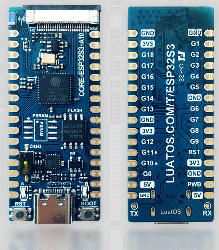
Dual-core Xtensa LX7 · 240MHz
512KB SRAM · 8MB PSRAM · 16MB flash
Built-in USB-JTAG · OpenOCD 0.12.0+
Part 2
접을 수 있는 영어 원문 전체
영어 원문 전체 펼치기
BBA961261CA833E228774E4B4360A3F730DB3C84AB591FB69B0F6F64C14081BA
.. _esp32s3_luatos_core:

ESP32S3-Luatos-Core
###################

Overview
********

The ESP32S3-LUATOS-CORE development board is a compact board based on Espressif ESP32-S3.
The board comes equipped with a 2.4GHz antenna and supports both Wi-Fi and Bluetooth functionalities.
For more information, check `ESP32S3-LUATOS-CORE`_ (chinese)

.. image:: ../../../../../../../boards/luatos/esp32s3_luatos_core/doc/img/esp32s3_luatos_core.jpg
     :align: center
     :alt: esp32s3_luatos_core

Hardware
********

ESP32-S3 is a low-power MCU-based system on a chip (SoC) with integrated 2.4 GHz Wi-Fi
and Bluetooth® Low Energy (Bluetooth LE). It consists of high-performance dual-core microprocessor
(Xtensa® 32-bit LX7), a low power coprocessor, a Wi-Fi baseband, a Bluetooth LE baseband,
RF module, and numerous peripherals.

ESP32S3-LUATOS-CORE includes the following features:

- Dual core 32-bit Xtensa Microprocessor (Tensilica LX7), running up to 240MHz
- Additional vector instructions support for AI acceleration
- 512KB of SRAM
- 384KB of ROM
- 8MB of PSRAM
- 16MB of FLASH
- Wi-Fi 802.11b/g/n
- Bluetooth LE 5.0 with long-range support and up to 2Mbps data rate

Digital interfaces:

- 4x SPI
- 1x LCD interface (8-bit ~16-bit parallel RGB, I8080 and MOTO6800), supporting conversion between RGB565, YUV422, YUV420 and YUV411
- 1x DVP 8-bit ~16-bit camera interface
- 3x UART
- 2x I2C
- 2x I2S
- 1x RMT (TX/RX)
- 1x pulse counter
- LED PWM controller, up to 8 channels
- 1x USB Port with USB switcher, supporting following modes:
  - 1x full-speed USB OTG or 1x USB Serial/JTAG controller
  - USB to serial chip CH343
- 2x MCPWM
- 1x SDIO host controller with 2 slots
- General DMA controller (GDMA), with 5 transmit channels and 5 receive channels
- 1x TWAI® controller, compatible with ISO 11898-1 (CAN Specification 2.0)
- 2x Blue LED

Analog interfaces:

- 2x 12-bit SAR ADCs, up to 20 channels

Timers:

- 4x 54-bit general-purpose timers
- 1x 52-bit system timer
- 3x watchdog timers

Low Power:

- Power Management Unit with five power modes
- Ultra-Low-Power (ULP) coprocessors: ULP-RISC-V and ULP-FSM

Security:

- Secure boot
- Flash encryption
- 4-Kbit OTP, up to 1792 bits for users
- Cryptographic hardware acceleration: (AES-128/256, Hash, RSA, RNG, HMAC, Digital signature)

For more information, check the datasheet at `ESP32-S3 Datasheet`_.

.. image:: ../../../../../../../boards/luatos/esp32s3_luatos_core/doc/img/esp32s3_luatos_core_pinout.jpg
     :align: center
     :alt: esp32s3_luatos_core_pinout

Supported Features
==================

Current Zephyr's ESP32S3-LUATOS-Core board supports the following features:

+------------+------------+-------------------------------------+
| Interface  | Controller | Driver/Component                    |
+============+============+=====================================+
| UART       | on-chip    | serial port                         |
+------------+------------+-------------------------------------+
| GPIO       | on-chip    | gpio                                |
+------------+------------+-------------------------------------+
| PINMUX     | on-chip    | pinmux                              |
+------------+------------+-------------------------------------+
| USB-JTAG   | on-chip    | hardware interface                  |
+------------+------------+-------------------------------------+
| SPI Master | on-chip    | spi                                 |
+------------+------------+-------------------------------------+
| TWAI/CAN   | on-chip    | can                                 |
+------------+------------+-------------------------------------+
| Timers     | on-chip    | counter                             |
+------------+------------+-------------------------------------+
| Watchdog   | on-chip    | watchdog                            |
+------------+------------+-------------------------------------+
| TRNG       | on-chip    | entropy                             |
+------------+------------+-------------------------------------+
| LEDC       | on-chip    | pwm                                 |
+------------+------------+-------------------------------------+
| MCPWM      | on-chip    | pwm                                 |
+------------+------------+-------------------------------------+
| PCNT       | on-chip    | qdec                                |
+------------+------------+-------------------------------------+
| GDMA       | on-chip    | dma                                 |
+------------+------------+-------------------------------------+
| USB-CDC    | on-chip    | serial                              |
+------------+------------+-------------------------------------+

Prerequisites
-------------

Espressif HAL requires WiFi and Bluetooth binary blobs in order work. Run the command
below to retrieve those files.

.. code-block:: console

   west blobs fetch hal_espressif

.. note::

   It is recommended running the command above after :file:`west update`.

Building & Flashing
*******************

Simple boot
===========

The board could be loaded using the single binary image, without 2nd stage bootloader.
It is the default option when building the application without additional configuration.

.. note::

   Simple boot does not provide any security features nor OTA updates.

MCUboot bootloader
==================

User may choose to use MCUboot bootloader instead. In that case the bootloader
must be build (and flash) at least once.

There are two options to be used when building an application:

1. Sysbuild
2. Manual build

.. note::

   User can select the MCUboot bootloader by adding the following line
   to the board default configuration file.

   .. code:: cfg

      CONFIG_BOOTLOADER_MCUBOOT=y

Sysbuild
========

The sysbuild makes possible to build and flash all necessary images needed to
bootstrap the board with the ESP32 SoC.

To build the sample application using sysbuild use the command:

.. zephyr-app-commands::
   :tool: west
   :app: samples/hello_world
   :board: esp32s3_luatos_core
   :goals: build
   :west-args: --sysbuild
   :compact:

By default, the ESP32 sysbuild creates bootloader (MCUboot) and application
images. But it can be configured to create other kind of images.

Build directory structure created by sysbuild is different from traditional
Zephyr build. Output is structured by the domain subdirectories:

.. code-block::

  build/
  ├── hello_world
  │   └── zephyr
  │       ├── zephyr.elf
  │       └── zephyr.bin
  ├── mcuboot
  │    └── zephyr
  │       ├── zephyr.elf
  │       └── zephyr.bin
  └── domains.yaml

.. note::

   With ``--sysbuild`` option the bootloader will be re-build and re-flash
   every time the pristine build is used.

For more information about the system build please read the :ref:`sysbuild` documentation.

Manual build
============

During the development cycle, it is intended to build & flash as quickly possible.
For that reason, images can be build one at a time using traditional build.

The instructions following are relevant for both manual build and sysbuild.
The only difference is the structure of the build directory.

.. note::

   Remember that bootloader (MCUboot) needs to be flash at least once.

Build and flash applications as usual (see :ref:`build_an_application` and
:ref:`application_run` for more details).

.. zephyr-app-commands::
   :zephyr-app: samples/hello_world
   :board: esp32s3_luatos_core/esp32s3/procpu
   :goals: build

If CH343 chip is disabled, You need use the following command to build:

.. zephyr-app-commands::
   :zephyr-app: samples/hello_world
   :board: esp32s3_luatos_core/esp32s3/procpu/usb
   :goals: build

The usual ``flash`` target will work with the ``esp32s3_luatos_core`` board
configuration. Here is an example for the :ref:`hello_world`
application.

.. zephyr-app-commands::
   :zephyr-app: samples/hello_world
   :board: esp32s3_luatos_core/esp32s3/procpu
   :goals: flash

Open the serial monitor using the following command:

.. code-block:: shell

   west espressif monitor

After the board has automatically reset and booted, you should see the following
message in the monitor:

.. code-block:: console

   ***** Booting Zephyr OS vx.x.x-xxx-gxxxxxxxxxxxx *****
   Hello World! esp32s3_luatos_core

Debugging
*********

ESP32-S3 support on OpenOCD is available upstream as of version 0.12.0.
Download and install OpenOCD from `OpenOCD`_.

ESP32-S3 has a built-in JTAG circuitry and can be debugged without any additional chip. Only an USB cable connected to the D+/D- pins is necessary.

Further documentation can be obtained from the SoC vendor in `JTAG debugging
for ESP32-S3`_.

Here is an example for building the :ref:`hello_world` application.

.. zephyr-app-commands::
   :zephyr-app: samples/hello_world
   :board: esp32s3_luatos_core/esp32s3/procpu
   :goals: build flash

You can debug an application in the usual way. Here is an example for the :ref:`hello_world` application.

.. zephyr-app-commands::
   :zephyr-app: samples/hello_world
   :board: esp32s3_luatos_core/esp32s3/procpu
   :goals: debug

.. _`JTAG debugging for ESP32-S3`: https://docs.espressif.com/projects/esp-idf/en/latest/esp32s3/api-guides/jtag-debugging/
.. _`OpenOCD`: https://github.com/openocd-org/openocd
.. _`ESP32S3-LUATOS-CORE`: https://wiki.luatos.com/chips/esp32s3/board.html

References
**********

.. _ESP32S3-LUATOS-CORE User Guide: https://wiki.luatos.com/chips/esp32s3/board.html
.. _ESP32-S3 Datasheet: https://www.espressif.com/sites/default/files/documentation/esp32-s3-mini-1_mini-1u_datasheet_en.pdf
.. _ESP32 Technical Reference Manual: https://www.espressif.com/sites/default/files/documentation/esp32-s3_technical_reference_manual_en.pdf
Part 3
한국어 전문 번역
개요
ESP32S3-LUATOS-CORE는 Espressif ESP32-S3 기반 compact development board입니다. 2.4GHz antenna를 장착하고 Wi-Fi와 Bluetooth를 지원합니다. 자세한 내용은 중국어 ESP32S3-LUATOS-CORE page에서 확인할 수 있습니다.
Hardware
ESP32-S3는 2.4GHz Wi-Fi와 Bluetooth Low Energy를 통합한 low-power MCU-based SoC입니다. High-performance dual-core Xtensa 32-bit LX7 microprocessor, low-power coprocessor, Wi-Fi·Bluetooth LE baseband, RF module과 여러 peripheral로 구성됩니다.
ESP32S3-LUATOS-CORE의 주요 기능은 다음과 같습니다.
- 최대 240MHz dual-core 32-bit Xtensa microprocessor(Tensilica LX7)
- AI acceleration용 추가 vector instruction
- 512KB SRAM, 384KB ROM, 8MB PSRAM, 16MB FLASH
- Wi-Fi 802.11b/g/n
- Long-range와 최대 2Mbps를 지원하는 Bluetooth LE 5.0
Digital interface
- SPI 4개
- 8~16-bit parallel RGB, I8080, MOTO6800과 RGB565·YUV422·YUV420·YUV411 변환을 지원하는 LCD interface 1개
- 8~16-bit DVP camera interface 1개
- UART 3개, I2C 2개, I2S 2개
- RMT(TX/RX) 1개와 pulse counter 1개
- 최대 8-channel LED PWM controller
- USB switcher를 갖춘 USB port 1개: full-speed USB OTG 또는 USB Serial/JTAG controller, USB-to-serial CH343
- MCPWM 2개
- 2-slot SDIO host controller 1개
- TX 5-channel·RX 5-channel General DMA controller(GDMA)
- ISO 11898-1(CAN Specification 2.0) compatible TWAI controller 1개
- Blue LED 2개
Analog interface
- 최대 20-channel 12-bit SAR ADC 2개
Timer
- 54-bit general-purpose timer 4개
- 52-bit system timer 1개
- Watchdog timer 3개
Low Power
- 5개 power mode를 제공하는 Power Management Unit
- ULP-RISC-V와 ULP-FSM Ultra-Low-Power coprocessor
Security
- Secure boot
- Flash encryption
- 4-Kbit OTP, user용 최대 1792 bits
- Cryptographic hardware acceleration: AES-128/256, Hash, RSA, RNG, HMAC, Digital signature
자세한 내용은 ESP32-S3 Datasheet를 참고하십시오.
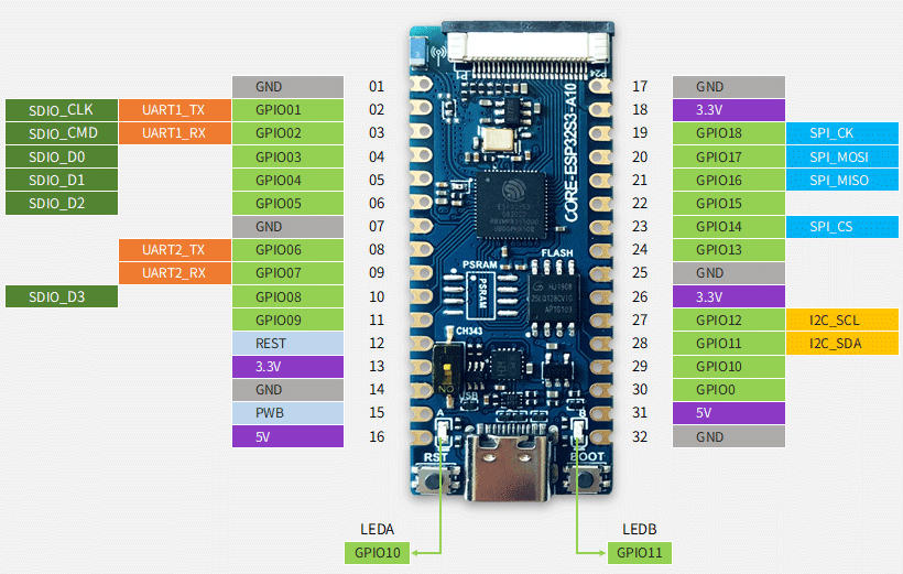
지원 기능
현재 Zephyr의 ESP32S3-LUATOS-Core board는 다음 기능을 지원합니다.
| Interface | Controller | Driver/Component |
|---|---|---|
| UART | on-chip | serial port |
| GPIO | on-chip | gpio |
| PINMUX | on-chip | pinmux |
| USB-JTAG | on-chip | hardware interface |
| SPI Master | on-chip | spi |
| TWAI/CAN | on-chip | can |
| Timers | on-chip | counter |
| Watchdog | on-chip | watchdog |
| TRNG | on-chip | entropy |
| LEDC | on-chip | pwm |
| MCPWM | on-chip | pwm |
| PCNT | on-chip | qdec |
| GDMA | on-chip | dma |
| USB-CDC | on-chip | serial |
Prerequisites
Espressif HAL이 동작하려면 WiFi와 Bluetooth binary blob이 필요합니다. 다음 명령으로 해당 파일을 가져옵니다.
west blobs fetch hal_espressifBuilding과 Flashing
Simple boot
2nd-stage bootloader 없이 single binary image로 board를 load할 수 있습니다. 별도 configuration 없이 application을 build할 때 사용하는 default option입니다.
MCUboot bootloader
대신 MCUboot bootloader를 선택할 수 있습니다. 이 경우 bootloader를 적어도 한 번 build하고 flash해야 합니다. Application은 Sysbuild 또는 Manual build 방식으로 만들 수 있습니다.
Board default configuration file에 다음 줄을 추가하면 MCUboot를 선택할 수 있습니다.
CONFIG_BOOTLOADER_MCUBOOT=ySysbuild
Sysbuild는 ESP32 SoC로 board를 bootstrap하는 데 필요한 모든 image를 함께 build하고 flash할 수 있게 합니다.
west build -b esp32s3_luatos_core --sysbuild samples/hello_world기본적으로 ESP32 sysbuild는 bootloader(MCUboot) image와 application image를 만들지만 다른 image 종류로 구성할 수도 있습니다. Build output은 전통적인 Zephyr build와 달리 domain subdirectory로 나뉩니다.
build/
├── hello_world
│   └── zephyr
│       ├── zephyr.elf
│       └── zephyr.bin
├── mcuboot
│   └── zephyr
│       ├── zephyr.elf
│       └── zephyr.bin
└── domains.yaml자세한 내용은 Zephyr Sysbuild 문서를 참고하십시오.
Manual build
Development cycle에서는 전통적인 build로 image를 한 번에 하나씩 빠르게 만들 수 있습니다. 아래 절차는 manual build와 sysbuild 모두에 적용되며 차이는 build directory 구조뿐입니다. MCUboot는 적어도 한 번 flash해야 합니다.
west build -b esp32s3_luatos_core/esp32s3/procpu samples/hello_worldCH343 chip을 비활성화한 경우에는 다음 board qualifier로 build해야 합니다.
west build -b esp32s3_luatos_core/esp32s3/procpu/usb samples/hello_worldesp32s3_luatos_core board configuration에서는 일반적인 flash target이 동작합니다.
west build -b esp32s3_luatos_core/esp32s3/procpu samples/hello_world
west flash
다음 명령으로 serial monitor를 엽니다.
west espressif monitorBoard가 자동으로 reset되고 boot하면 monitor에 다음 message가 표시되어야 합니다.
***** Booting Zephyr OS vx.x.x-xxx-gxxxxxxxxxxxx *****
Hello World! esp32s3_luatos_core
Debugging
ESP32-S3 support는 OpenOCD version 0.12.0부터 upstream에서 사용할 수 있습니다. OpenOCD를 내려받아 install하십시오.
ESP32-S3에는 built-in JTAG circuitry가 있으므로 추가 chip 없이 debug할 수 있습니다. D+/D- pin에 연결한 USB cable만 필요합니다. 자세한 내용은 JTAG debugging for ESP32-S3을 참고하십시오.
west build -b esp32s3_luatos_core/esp32s3/procpu samples/hello_world
west flash
Application은 일반적인 방식으로 debug할 수 있습니다.
west build -b esp32s3_luatos_core/esp32s3/procpu samples/hello_world
west debug
참고 자료
Source
출처
영어 원문에는 문단, 문서 지시문, 표, 코드, 코드 심벌, 경로를 그대로 보존했습니다.