Part 1
요약·해설
ESP32-PICO-D4의 두 core와 SX1276·SX1278 LoRa frontend를 Zephyr sysbuild·MCUboot로 실행합니다.
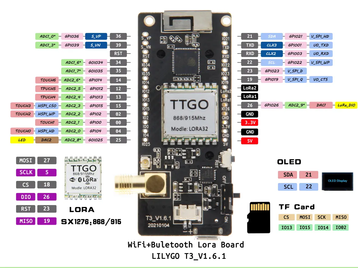
ESP32-PICO-D4 · 240MHz dual core
SX1278 433MHz · SX1276 868/915/923MHz
SSD1306 · 128x64 OLED
Part 2
접을 수 있는 영어 원문 전체
영어 원문 전체 펼치기
B121E2705D4E254F6A79679CC691AF2612CB7A3F9A297E2943EA8773B33A284B
.. _ttgo_lora32:

Lilygo TTGO LoRa32
##################

Overview
********

The Lilygo TTGO LoRa32 is a development board for LoRa applications baesed on the ESP32-PICO-D4.

It's available in two versions supporting two different frequency ranges and features the following integrated components:

- ESP32-PICO-D4 chip (240MHz dual core, 600 DMIPS, 520KB SRAM, Wi-Fi)
- SSD1306, 128x64 px, 0.96" screen
- SX1278 (433MHz) or SX1276 (868/915/923MHz) LoRa radio frontend
- JST GH 2-pin battery connector
- TF card slot

Some of the ESP32 I/O pins are accessible on the board's pin headers.

.. figure:: ../../../../../../../boards/lilygo/ttgo_lora32/doc/img/ttgo_lora32.webp
        :align: center
        :alt: Lilygo TTGO LoRa32 module
        :width: 400 px

        Lilygo TTGO LoRa32 module

Functional Description
**********************

The following table below describes the key components, interfaces, and controls
of the Lilygo TTGO LoRa32 board.

.. _SX127x: https://www.semtech.com/products/wireless-rf/lora-connect/sx1276#documentation
.. _ESP32-PICO-D4: https://www.espressif.com/sites/default/files/documentation/esp32-pico-d4_datasheet_en.pdf
.. _SSD1306: https://cdn-shop.adafruit.com/datasheets/SSD1306.pdf

+------------------+-------------------------------------------------------------------------+
| Key Component    | Description                                                             |
+==================+=========================================================================+
| ESP32-PICO-D4    | This `ESP32-PICO-D4`_ module provides complete Wi-Fi and Bluetooth      |
|                  | functionalities and integrates a 4-MB SPI flash.                        |
+------------------+-------------------------------------------------------------------------+
| Diagnostic LED   | One user LED connected to the GPIO pin.                                 |
+------------------+-------------------------------------------------------------------------+
| USB Port         | USB interface. Power supply for the board as well as the                |
|                  | serial communication interface between a computer and the board.        |
|                  | Micro-USB type connector.                                               |
+------------------+-------------------------------------------------------------------------+
| Power Switch     | Sliding power switch.                                                   |
+------------------+-------------------------------------------------------------------------+
| LCD screen       | Built-in OLED display \(`SSD1306`_, 0.96", 128x64 px\) controlled       |
|                  | by I2C interface                                                        |
+------------------+-------------------------------------------------------------------------+
| SX1276/SX1278    | LoRa radio frontend chip, connected via SPI.                            |
|                  | Use SX1276 for 433MHz and SX1276 for 868/915/923MHz.                    |
+------------------+-------------------------------------------------------------------------+
| TF card slot     | TF card slot wired to the SD interface of the MCU.                      |
+------------------+-------------------------------------------------------------------------+


Start Application Development
*****************************

Before powering up your Lilygo TTGO LoRa32, please make sure that the board is in good
condition with no obvious signs of damage.

System requirements
*******************

Prerequisites
=============

Espressif HAL requires WiFi and Bluetooth binary blobs in order work. Run the command
below to retrieve those files.

.. code-block:: console

   west blobs fetch hal_espressif

.. note::

   It is recommended running the command above after :file:`west update`.

Building & Flashing
*******************

Simple boot
===========

The board could be loaded using the single binary image, without 2nd stage bootloader.
It is the default option when building the application without additional configuration.

.. note::

   Simple boot does not provide any security features nor OTA updates.

MCUboot bootloader
==================

User may choose to use MCUboot bootloader instead. In that case the bootloader
must be build (and flash) at least once.

There are two options to be used when building an application:

1. Sysbuild
2. Manual build

.. note::

   User can select the MCUboot bootloader by adding the following line
   to the board default configuration file.

   .. code-block:: cfg

      CONFIG_BOOTLOADER_MCUBOOT=y

Sysbuild
========

The sysbuild makes possible to build and flash all necessary images needed to
bootstrap the board with the ESP32-PICO-D4 SoC.

To build the sample application using sysbuild use the command:

.. zephyr-app-commands::
   :tool: west
   :app: samples/hello_world
   :board: ttgo_lora32/esp32/procpu
   :goals: build
   :west-args: --sysbuild
   :compact:

By default, the ESP32-PICO-D4 sysbuild creates bootloader (MCUboot) and application
images. But it can be configured to create other kind of images.

Build directory structure created by sysbuild is different from traditional
Zephyr build. Output is structured by the domain subdirectories:

.. code-block::

  build/
  ├── hello_world
  │   └── zephyr
  │       ├── zephyr.elf
  │       └── zephyr.bin
  ├── mcuboot
  │    └── zephyr
  │       ├── zephyr.elf
  │       └── zephyr.bin
  └── domains.yaml

.. note::

   With ``--sysbuild`` option the bootloader will be re-build and re-flash
   every time the pristine build is used.

For more information about the system build please read the :ref:`sysbuild` documentation.

Manual build
============

During the development cycle, it is intended to build & flash as quickly possible.
For that reason, images can be build one at a time using traditional build.

The instructions following are relevant for both manual build and sysbuild.
The only difference is the structure of the build directory.

.. note::

   Remember that bootloader (MCUboot) needs to be flash at least once.

Build and flash applications as usual (see :ref:`build_an_application` and
:ref:`application_run` for more details).

.. zephyr-app-commands::
   :zephyr-app: samples/hello_world
   :board: ttgo_lora32/esp32/procpu
   :goals: build

The usual ``flash`` target will work with the ``ttgo_lora32`` board
configuration. Here is an example for the :ref:`hello_world`
application.

.. zephyr-app-commands::
   :zephyr-app: samples/hello_world
   :board: ttgo_lora32/esp32/procpu
   :goals: flash

The default baud rate for the Lilygo TTGO LoRa32 is set to 1500000bps. If experiencing issues when flashing,
try using different values by using ``--esp-baud-rate <BAUD>`` option during
``west flash`` (e.g. ``west flash --esp-baud-rate 115200``).

You can also open the serial monitor using the following command:

.. code-block:: shell

   west espressif monitor

After the board has automatically reset and booted, you should see the following
message in the monitor:

.. code-block:: console

   ***** Booting Zephyr OS vx.x.x-xxx-gxxxxxxxxxxxx *****
   Hello World! ttgo_lora32

LoRa samples
============

There are two LoRa samples that will work out of the box with this board.

To build the LoRa transmit sample application using sysbuild use the command:

.. zephyr-app-commands::
   :tool: west
   :app: samples/drivers/lora/send
   :board: ttgo_lora32/esp32/procpu
   :goals: build
   :west-args: --sysbuild
   :compact:

To build the LoRa receive sample application using sysbuild use the command:

.. zephyr-app-commands::
   :tool: west
   :app: samples/drivers/lora/receive
   :board: ttgo_lora32/esp32/procpu
   :goals: build
   :west-args: --sysbuild
   :compact:

Debugging
*********

Lilygo TTGO LoRa32 debugging is not supported due to pinout limitations.

Related Documents
*****************
- `Lilygo TTGO LoRa32 schematic <https://github.com/Xinyuan-LilyGO/LilyGo-LoRa-Series/blob/master/schematic/T3_V1.6.1.pdf>`_ (PDF)
- `Lilygo TTGO LoRa32 documentation <https://www.lilygo.cc/products/lora3>`_
- `Lilygo github repo <https://github.com/Xinyuan-LilyGo>`_
- `ESP32-PICO-D4 Datasheet <https://www.espressif.com/sites/default/files/documentation/esp32-pico-d4_datasheet_en.pdf>`_ (PDF)
- `ESP32 Datasheet <https://www.espressif.com/sites/default/files/documentation/esp32_datasheet_en.pdf>`_ (PDF)
- `ESP32 Hardware Reference <https://docs.espressif.com/projects/esp-idf/en/latest/esp32/hw-reference/index.html>`_
Part 3
한국어 전문 번역
개요
Lilygo TTGO LoRa32는 ESP32-PICO-D4 기반 LoRa application development board입니다.
서로 다른 주파수 범위를 지원하는 두 version이 있으며 다음 component를 통합합니다.
- ESP32-PICO-D4 chip: 240MHz dual core, 600 DMIPS, 520KB SRAM, Wi-Fi
- SSD1306 0.96-inch 128x64 px screen
- SX1278 433MHz 또는 SX1276 868/915/923MHz LoRa radio frontend
- JST GH 2-pin battery connector
- TF card slot
ESP32 I/O pin 일부는 board pin header에 연결되어 있습니다.
기능 설명
다음 표는 Lilygo TTGO LoRa32 board의 주요 component, interface와 control을 설명합니다.
| Key Component | Description |
|---|---|
| ESP32-PICO-D4 | 완전한 Wi-Fi와 Bluetooth 기능을 제공하며 4-MB SPI flash를 통합합니다. |
| Diagnostic LED | GPIO pin에 연결된 user LED 1개입니다. |
| USB Port | Board 전원과 computer-board 사이 serial 통신을 제공하는 Micro-USB connector입니다. |
| Power Switch | Sliding power switch입니다. |
| LCD screen | I2C interface로 제어하는 built-in OLED display(SSD1306, 0.96-inch, 128x64 px)입니다. |
| SX1276/SX1278 | SPI로 연결된 LoRa radio frontend chip입니다. 원문 표는 433MHz에 SX1276, 868/915/923MHz에도 SX1276을 사용한다고 적습니다. |
| TF card slot | MCU의 SD interface에 연결된 TF card slot입니다. |
Application development 시작
Lilygo TTGO LoRa32에 전원을 넣기 전에 board 상태가 양호하고 눈에 띄는 손상이 없는지 확인하십시오.
System requirements
Prerequisites
Espressif HAL이 동작하려면 WiFi와 Bluetooth binary blob이 필요합니다. 다음 명령으로 해당 파일을 가져옵니다.
west blobs fetch hal_espressifBuilding과 Flashing
Simple boot
2nd-stage bootloader 없이 single binary image로 board를 load할 수 있습니다. 별도 configuration 없이 application을 build할 때 사용하는 default option입니다.
MCUboot bootloader
대신 MCUboot bootloader를 선택할 수 있습니다. 이 경우 bootloader를 적어도 한 번 build하고 flash해야 합니다.
Application build 방식은 Sysbuild와 Manual build 두 가지입니다. Board default configuration file에 다음 줄을 추가하면 MCUboot를 선택할 수 있습니다.
CONFIG_BOOTLOADER_MCUBOOT=ySysbuild
Sysbuild는 ESP32-PICO-D4 SoC로 board를 bootstrap하는 데 필요한 모든 image를 함께 build하고 flash할 수 있게 합니다. Sample application은 다음과 같이 build합니다.
west build -b ttgo_lora32/esp32/procpu --sysbuild samples/hello_world기본적으로 ESP32-PICO-D4 sysbuild는 bootloader(MCUboot) image와 application image를 만듭니다. 다른 종류의 image를 만들도록 구성할 수도 있습니다.
Sysbuild의 build directory는 전통적인 Zephyr build와 다르며 domain별 subdirectory로 구성됩니다.
build/
├── hello_world
│   └── zephyr
│       ├── zephyr.elf
│       └── zephyr.bin
├── mcuboot
│   └── zephyr
│       ├── zephyr.elf
│       └── zephyr.bin
└── domains.yaml자세한 내용은 Zephyr Sysbuild 문서를 참고하십시오.
Manual build
Development cycle에서는 가능한 한 빨리 build하고 flash해야 하므로 전통적인 build로 image를 한 번에 하나씩 만들 수 있습니다. 아래 지침은 manual build와 sysbuild 모두에 적용되며 차이는 build directory 구조뿐입니다.
일반적인 Zephyr application과 같은 방식으로 build하고 flash합니다.
west build -b ttgo_lora32/esp32/procpu samples/hello_worldttgo_lora32 board configuration에서는 일반적인 flash target이 동작합니다. hello_world 예는 다음과 같습니다.
west build -b ttgo_lora32/esp32/procpu samples/hello_world
west flash
Default baud rate는 1500000bps입니다. Flashing에 문제가 있으면 west flash에 --esp-baud-rate <BAUD> option을 사용해 다른 값을 시도하십시오. 예: west flash --esp-baud-rate 115200.
다음 명령으로 serial monitor를 열 수 있습니다.
west espressif monitorBoard가 자동으로 reset되고 boot하면 monitor에 다음 message가 표시되어야 합니다.
***** Booting Zephyr OS vx.x.x-xxx-gxxxxxxxxxxxx *****
Hello World! ttgo_lora32
LoRa sample
이 board에서 별도 변경 없이 동작하는 LoRa sample은 두 개입니다. Sysbuild로 LoRa transmit sample을 build합니다.
west build -b ttgo_lora32/esp32/procpu --sysbuild samples/drivers/lora/sendSysbuild로 LoRa receive sample을 build합니다.
west build -b ttgo_lora32/esp32/procpu --sysbuild samples/drivers/lora/receiveDebugging
Lilygo TTGO LoRa32는 pinout 제한 때문에 debugging을 지원하지 않습니다.
관련 문서
Source
출처
영어 원문에는 문단, 문서 지시문, 표, 코드, 코드 심벌, 경로를 그대로 보존했습니다.