Part 1
요약·해설
GD32F450V-START는 3MiB Flash, 256KiB SRAM과 onboard GD-Link를 제공하며 serial connector는 직접 구성해야 합니다.
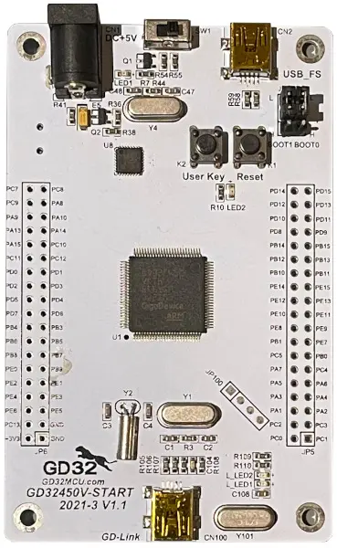
Cortex-M4F · 200MHz
82
PB6/PB7 · JP6 soldering
Part 2
접을 수 있는 영어 원문 전체
영어 원문 전체 펼치기
31E4453E59A3215C217C4642A5B77C3B6D93E46709D95AA02A6B361969540F22
.. _gd32f450v_start:

GigaDevice GD32F450V-START
##########################

Overview
********

The GD32F450V-START board is a hardware platform that enables prototyping
on GD32F450VK Cortex-M4F Stretch Performance MCU.

The GD32F450VK features a single-core ARM Cortex-M4F MCU which can run up
to 200 MHz with flash accesses zero wait states, 3072kiB of Flash, 256kiB of
SRAM and 82 GPIOs.

.. image:: ../../../../../../../boards/gd/gd32f450v_start/doc/img/gd32f450v_start.webp
     :align: center
     :alt: gd32f450v_start

Hardware
********

- GD32F450VKT6 MCU
- 1 x User LEDs
- 1 x User Push buttons
- USB FS/HS connectors
- GD-Link on board programmer
- J-Link/SWD connector

For more information about the GD32F450 SoC and GD32F450V-START board:

- `GigaDevice Cortex-M4F Stretch Performance SoC Website`_
- `GD32F450X Datasheet`_
- `GD32F4XX User Manual`_
- `GD32F450V-START User Manual`_

Supported Features
==================

The board configuration supports the following hardware features:

.. list-table::
   :header-rows: 1

   * - Peripheral
     - Kconfig option
     - Devicetree compatible
   * - EXTI
     - :kconfig:option:`CONFIG_GD32_EXTI`
     - :dtcompatible:`gd,gd32-exti`
   * - GPIO
     - :kconfig:option:`CONFIG_GPIO`
     - :dtcompatible:`gd,gd32-gpio`
   * - NVIC
     - N/A
     - :dtcompatible:`arm,v8m-nvic`
   * - PWM
     - :kconfig:option:`CONFIG_PWM`
     - :dtcompatible:`gd,gd32-pwm`
   * - SYSTICK
     - N/A
     - N/A
   * - USART
     - :kconfig:option:`CONFIG_SERIAL`
     - :dtcompatible:`gd,gd32-usart`

Other peripherals may be used if shields are connected to the board.

Serial Port
===========

The GD32F450V-START board has no exposed serial communication port. The board
provides default configuration for USART0 with TX connected at PB6 and RX at
PB7. PB6/PB7 are exposed in JP6, so you can solder a connector and use a
UART-USB adapter.

Programming and Debugging
*************************

Before programming your board make sure to configure boot jumpers as
follows:

- JP2/3: Select 2-3 for both (boot from user memory)

Using GD-Link
=============

The GD32F450V-START includes an onboard programmer/debugger (GD-Link) which
allows flash programming and debugging over USB. There is also a SWD header
(JP100) which can be used with tools like Segger J-Link.

#. Build the Zephyr kernel and the :ref:`hello_world` sample application:

   .. zephyr-app-commands::
      :zephyr-app: samples/hello_world
      :board: gd32f450v_start
      :goals: build
      :compact:

#. Run your favorite terminal program to listen for output. On Linux the
   terminal should be something like ``/dev/ttyUSB0``. For example:

   .. code-block:: console

      minicom -D /dev/ttyUSB0 -o

   The -o option tells minicom not to send the modem initialization
   string. Connection should be configured as follows:

      - Speed: 115200
      - Data: 8 bits
      - Parity: None
      - Stop bits: 1

#. To flash an image:

   .. zephyr-app-commands::
      :zephyr-app: samples/hello_world
      :board: gd32f450v_start
      :goals: flash
      :compact:

   You should see "Hello World! gd32f450v_start" in your terminal.

#. To debug an image:

   .. zephyr-app-commands::
      :zephyr-app: samples/hello_world
      :board: gd32f450v_start
      :goals: debug
      :compact:

.. _GigaDevice Cortex-M4F Stretch Performance SoC Website:
   https://www.gigadevice.com/products/microcontrollers/gd32/arm-cortex-m4/stretch-performance-line/

.. _GD32F450X Datasheet:
   https://gd32mcu.com/data/documents/datasheet/GD32F450xx_Datasheet_Rev2.3.pdf

.. _GD32F4xx User Manual:
   https://www.gigadevice.com/manual/gd32f450xxxx-user-manual/

.. _GD32F450V-START User Manual:
   https://gd32mcu.com/data/documents/evaluationBoard/GD32F4xx_Demo_Suites_V2.6.1.rar
Part 3
한국어 전문 번역
개요
GD32F450V-START board는 GD32F450VK Cortex-M4F stretch-performance MCU로 prototype을 제작할 수 있는 hardware platform입니다.
GD32F450VK에는 최대 200MHz로 동작하는 single-core ARM Cortex-M4F MCU가 들어 있습니다. Flash 접근은 zero wait state이며 3072KiB Flash, 256KiB SRAM, GPIO 82개를 제공합니다.
Hardware
- GD32F450VKT6 MCU
- User LED 1개
- User push button 1개
- USB FS/HS connector
- Onboard GD-Link programmer
- J-Link/SWD connector
GD32F450 SoC와 board의 자세한 내용은 product page, datasheet와 user manual에서 확인할 수 있습니다.
지원 기능
Board configuration은 다음 hardware 기능을 지원합니다.
| 주변장치 | Kconfig option | Devicetree compatible |
|---|---|---|
| EXTI | CONFIG_GD32_EXTI | gd,gd32-exti |
| GPIO | CONFIG_GPIO | gd,gd32-gpio |
| NVIC | N/A | arm,v8m-nvic |
| PWM | CONFIG_PWM | gd,gd32-pwm |
| SYSTICK | N/A | N/A |
| USART | CONFIG_SERIAL | gd,gd32-usart |
Shield를 연결하면 다른 peripheral도 사용할 수 있습니다.
Serial port
GD32F450V-START에는 외부에 노출된 serial communication port가 없습니다. Default configuration은 TX가 PB6, RX가 PB7에 연결된 USART0을 제공합니다. PB6/PB7은 JP6에 노출되므로 connector를 납땜한 뒤 UART-USB adapter를 사용할 수 있습니다.
Programming과 Debugging
Programming 전에 JP2/3을 모두 2-3으로 선택해 user memory에서 boot하도록 설정합니다.
GD-Link 사용
Onboard GD-Link는 USB flash programming과 debugging을 지원합니다. JP100 SWD header에는 Segger J-Link 같은 tool도 연결할 수 있습니다.
- Zephyr kernel과
hello_worldsample을 build합니다.west build -b gd32f450v_start samples/hello_world - Linux의
/dev/ttyUSB0같은 terminal에서 output을 받습니다.minicom -D /dev/ttyUSB0 -o-o는 modem initialization string을 보내지 않습니다. Connection 설정은 다음과 같습니다.- Speed: 115200
- Data: 8 bits
- Parity: None
- Stop bits: 1
- Image를 flash합니다.
west flashHello World! gd32f450v_start가 terminal에 표시되어야 합니다. - Image를 debug합니다.
west debug
참고 자료
Source
출처
영어 원문에는 문단, 문서 지시문, 표, 코드, 코드 심벌, 경로를 그대로 보존했습니다.