Part 1
요약·해설
ESP-WROVER-KIT는 64-Mbit PSRAM module, LCD·MicroSD·camera connector와 내장 FT2232HL programmer/debugger를 갖춘 종합 ESP32 개발 보드입니다.
ESP32-WROVER-E · 64-Mbit PSRAM
LCD · MicroSD · camera
FT2232HL · USB-JTAG
Part 2
접을 수 있는 영어 원문 전체
영어 원문 전체 펼치기
AE69388847F73ECD8D8E1D5F26632D7D8FABB98425F83FE1C95DB63FC238E6D1
.. _esp_wrover_kit:

ESP-WROVER-KIT
##############

Overview
********

ESP-WROVER-KIT is an ESP32-based development board produced by `Espressif <https://www.espressif.com/>`_.

ESP-WROVER-KIT features the following integrated components:

- ESP32-WROVER-E module
- LCD screen
- MicroSD card slot

Its another distinguishing feature is the embedded FTDI FT2232HL chip - an advanced multi-interface
USB bridge. This chip enables to use JTAG for direct debugging of ESP32 through the USB interface
without a separate JTAG debugger. ESP-WROVER-KIT makes development convenient, easy, and
cost-effective.

Most of the ESP32 I/O pins are broken out to the board's pin headers for easy access.

.. note::

   ESP32's GPIO16 and GPIO17 are used as chip select and clock signals for PSRAM. By default, the two
   GPIOs are not broken out to the board's pin headers in order to ensure reliable performance.

Functionality Overview
**********************

The block diagram below shows the main components of ESP-WROVER-KIT and their interconnections.

.. image:: ../../../../../../../boards/espressif/esp_wrover_kit/doc/img/esp-wrover-kit-block-diagram.jpg
     :align: center
     :alt: ESP-WROVER-KIT

Functional Description
**********************

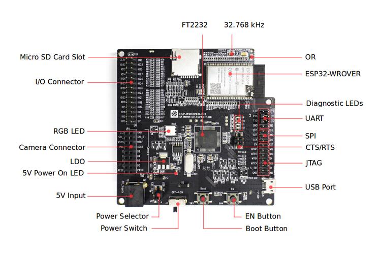
The following two figures and the table below describe the key components, interfaces, and controls
of the ESP-WROVER-KIT board.

.. figure:: ../../../../../../../boards/espressif/esp_wrover_kit/doc/img/esp-wrover-kit-v4.1-layout-front.jpg
     :align: center
     :alt: esp wrover front

     ESP-WROVER-KIT board layout - front

.. _esp wrover back:

.. figure:: ../../../../../../../boards/espressif/esp_wrover_kit/doc/img/esp-wrover-kit-v4.1-layout-back.jpg
     :align: center
     :alt: esp wrover back

     ESP-WROVER-KIT board layout - back

The table below provides description in the following manner:
- Starting from the first picture’s top right corner and going clockwise
- Then moving on to the second picture

+------------------+-------------------------------------------------------------------------+
| Key Component    | Description                                                             |
+==================+=========================================================================+
| FT2232           | The FT2232 chip serves as a multi-protocol USB-to-serial bridge         |
|                  | which can be programmed and controlled via USB to provide               |
|                  | communication with ESP32. FT2232 also features USB-to-JTAG              |
|                  | interface which is available on channel A of the chip, while USB-to-    |
|                  | serial is on channel B. The FT2232 chip enhances user-friendliness in   |
|                  | terms of application development and debugging. See `ESP-WROVER-KIT     |
|                  | V4.1 schematic                                                          |
|                  | <https://dl.espressif.com/dl/schematics/ESP-WROVER-KIT_V4_1.pdf>`_.     |
+------------------+-------------------------------------------------------------------------+
| 32.768 kHz       | External precision 32.768 kHz crystal oscillator serves as a clock with |
|                  | low-power consumption while the chip is in Deep-sleep mode.             |
+------------------+-------------------------------------------------------------------------+
| 0R               | Zero-ohm resistor intended as a placeholder for a current shunt, can    |
|                  | be desoldered or replaced with a current shunt to facilitate the        |
|                  | measurement of ESP32’s current consumption in different modes.          |
+------------------+-------------------------------------------------------------------------+
| ESP32-WROVER-E   | This ESP32 module features 64-Mbit PSRAM for flexible extended          |
| module           | storage and data processing capabilities.                               |
+------------------+-------------------------------------------------------------------------+
| Diagnostic LEDs  | Four red LEDs connected to the GPIO pins of FT2232. Intended for        |
|                  | future use.                                                             |
+------------------+-------------------------------------------------------------------------+
| UART             | Serial port. The serial TX/RX signals of FT2232 and ESP32 are broken    |
|                  | out to the inward and outward sides of JP2 respectively. By default,    |
|                  | these pairs of pins are connected with jumpers. To use ESP32’s serial   |
|                  | interface, remove the jumpers and connect another external serial       |
|                  | device to the respective pins.                                          |
+------------------+-------------------------------------------------------------------------+
| SPI              | By default, ESP32 uses its SPI interface to access flash and PSRAM      |
|                  | memory inside the module. Use these pins to connect ESP32 to            |
|                  | another SPI device. In this case, an extra chip select (CS) signal is   |
|                  | needed. Please note that the voltage of this interface is 3.3 V.        |
+------------------+-------------------------------------------------------------------------+
| CTS/RTS          | Serial port flow control signals: the pins are not connected to the     |
|                  | circuitry by default. To enable them, short the respective pins of JP14 |
|                  | with jumpers.                                                           |
+------------------+-------------------------------------------------------------------------+
| JTAG             | JTAG interface. JTAG signals of FT2232 and ESP32 are broken out to      |
|                  | the inward and outward sides of JP2 respectively. By default, these     |
|                  | pairs of pins are disconnected. To enable JTAG, short the respective    |
|                  | pins with jumpers as shown in Section                                   |
|                  | :ref:`Setup Options<setup options>`                                     |
+------------------+-------------------------------------------------------------------------+
| USB Port         | USB interface. Power supply for the board as well as the                |
|                  | communication interface between a computer and the board.               |
+------------------+-------------------------------------------------------------------------+
| EN Button        | Reset button.                                                           |
+------------------+-------------------------------------------------------------------------+
| BOOT Button      | Download button. Holding down Boot and then pressing EN initiates       |
|                  | Firmware Download mode for downloading firmware through the             |
+------------------+-------------------------------------------------------------------------+
| Power Switch     | Power On/Off Switch. Toggling toward the Boot button powers the         |
|                  | board on, toggling away from Boot powers the board off.                 |
+------------------+-------------------------------------------------------------------------+
| Power Selector   | Power supply selector interface. The board can be powered either via    |
|                  | USB or via the 5V Input interface. Select the power source with a       |
|                  | jumper. For more details, see Section Setup Options, jumper header      |
|                  | JP7.                                                                    |
+------------------+-------------------------------------------------------------------------+
| 5V input         | 5V power supply interface for a standard coaxial power connector,       |
|                  | 5.5 x 2.1 mm, center positive. This interface can be more convenient    |
|                  | when the board is operating autonomously (not connected to a            |
|                  | computer).                                                              |
+------------------+-------------------------------------------------------------------------+
| 5V Power On LED  | This red LED turns on when power is supplied to the board, either       |
|                  | from USB or 5V Input.                                                   |
+------------------+-------------------------------------------------------------------------+
| LDO              | NCP1117(1A). 5V-to-3.3V LDO. NCP1117 can provide a maximum              |
|                  | current of 1A. The LDO on the board has a fixed output voltage.         |
|                  | Although, the user can install an LDO with adjustable output voltage.   |
|                  | For details, please refer to `ESP-WROVER-KIT V4.1 schematic             |
|                  | <https://dl.espressif.com/dl/schematics/ESP-WROVER-KIT_V4_1.pdf>`_.     |
+------------------+-------------------------------------------------------------------------+
| Camera Connector | Camera interface, a standard OV7670 camera module.                      |
+------------------+-------------------------------------------------------------------------+
| RGB LED          | Red, green and blue (RGB) light emitting diodes (LEDs), can be          |
|                  | controlled by pulse width modulation (PWM).                             |
+------------------+-------------------------------------------------------------------------+
| I/O Connector    | All the pins on the ESP32 module are broken out to pin headers. You     |
|                  | can program ESP32 to enable multiple functions, such as PWM, ADC,       |
|                  | DAC, I2C, I2S, SPI, etc.                                                |
+------------------+-------------------------------------------------------------------------+
| MicroSD Card     | Useful for developing applications that access MicroSD card for data    |
| Slot             | storage and retrieval.                                                  |
+------------------+-------------------------------------------------------------------------+
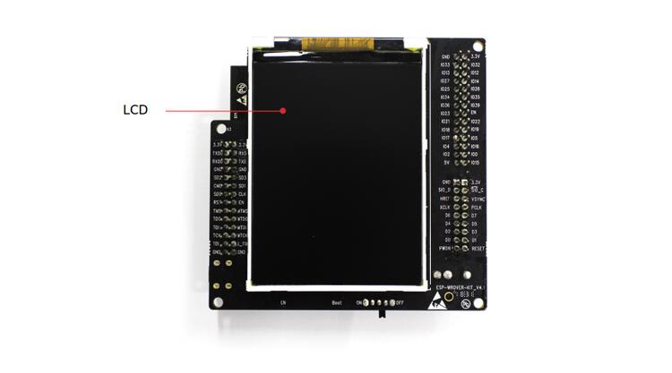
| LCD              | Support for mounting and interfacing a 3.2” SPI (standard 4-wire        |
|                  | Serial Peripheral Interface) LCD, as shown on figure                    |
|                  | :ref:`ESP-WROVER-KIT board layout - back<esp wrover back>`              |
+------------------+-------------------------------------------------------------------------+

.. _setup options:

Setup Options
*************

There are three jumper blocks available to set up the board functionality. The most frequently
required options are listed in the table below.

.. |jmpextpwr| image:: img/esp-wrover-kit-v4.1-jp7-ext_5v.jpg

.. |jmpusbpwr| image:: img/esp-wrover-kit-v4.1-jp7-usb_5v.jpg

.. |jmpjtag| image:: img/esp-wrover-kit-v4.1-jp2-jtag.jpg

.. |jmpuart| image:: img/esp-wrover-kit-v4.1-jp2-tx-rx.jpg

.. |jmpctrl| image:: img/esp-wrover-kit-v4.1-jp14.jpg

+------------------+--------------------------------------------------------------+
| Header | Jumper Setting | Description of Functionality                          |
+========+================+=======================================================+
| JP7    | |jmpextpwr|    | Power ESP-WROVER-KIT via an external power supply     |
+--------+----------------+-------------------------------------------------------+
| JP7    | |jmpusbpwr|    | Power ESP-WROVER-KIT via USB                          |
+--------+----------------+-------------------------------------------------------+
| JP2    | |jmpjtag|      | Enable JTAG functionality                             |
+--------+----------------+-------------------------------------------------------+
| JP2    | |jmpuart|      | Enable UART communication                             |
+--------+----------------+-------------------------------------------------------+
| JP14   | |jmpctrl|      | Enable RTS/CTS flow control for serial communication  |
+--------+----------------+-------------------------------------------------------+

Allocation of ESP32 Pins
************************

Some pins / terminals of ESP32 are allocated for use with the onboard or external hardware. If
that hardware is not used, e.g., nothing is plugged into the Camera (JP4) header, then these
GPIOs can be used for other purposes.

Some of the pins, such as GPIO0 or GPIO2, have multiple functions and some of them are shared
among onboard and external peripheral devices. Certain combinations of peripherals cannot work
together. For example, it is not possible to do JTAG debugging of an application that is using
SD card, because several pins are shared by JTAG and the SD card slot.

In other cases, peripherals can coexist under certain conditions. This is applicable to, for
example, LCD screen and SD card that share only a single pin GPIO21. This pin is used to provide
D/C (Data / Control) signal for the LCD as well as the Card Detect signal read from the SD card
slot. If the card detect functionality is not essential, then it may be disabled by removing R167,
so both LCD and SD may operate together.

For more details on which pins are shared among which peripherals, please refer to the table in
the next section.

Main I/O Connector / JP1
************************

The JP1 connector consists of 14x2 male pins whose functions are shown in the middle two “I/O”
columns of the table below. The two “Shared With” columns on both sides describe where else on
the board a certain GPIO is used.

+-------------------+------+------+----------------------+
| Shared With       | I/O  | I/O  | Shared With          |
+===================+======+======+======================+
| n/a               | 3.3V | GND  | n/a                  |
+-------------------+------+------+----------------------+
| NC/XTAL           | IO32 | IO33 | NC/XTAL              |
+-------------------+------+------+----------------------+
| JTAG, MicroSD     | IO12 | IO13 | JTAG, MicroSD        |
+-------------------+------+------+----------------------+
| JTAG, MicroSD     | IO14 | IO27 | Camera               |
+-------------------+------+------+----------------------+
| Camera            | IO26 | IO25 | Camera, LCD          |
+-------------------+------+------+----------------------+
| Camera            | IO35 | IO34 | Camera               |
+-------------------+------+------+----------------------+
| Camera            | IO39 | IO36 | Camera               |
+-------------------+------+------+----------------------+
| JTAG              | EN   | IO23 | Camera, LCD          |
+-------------------+------+------+----------------------+
| Camera, LCD       | IO22 | IO21 | Camera, LCD, MicroSD |
+-------------------+------+------+----------------------+
| Camera, LCD       | IO19 | IO18 | Camera, LCD          |
+-------------------+------+------+----------------------+
| Camera, LCD       | IO5  | IO17 | PSRAM                |
+-------------------+------+------+----------------------+
| PSRAM             | IO16 | IO4  | LED, Camera, MicroSD |
+-------------------+------+------+----------------------+
| Camera, LED, Boot | IO0  | IO2  | LED, MicroSD         |
+-------------------+------+------+----------------------+
| JTAG, MicroSD     | IO15 | 5V   |                      |
+-------------------+------+------+----------------------+

Legend:

  - NC/XTAL - 32.768 kHz Oscillator
  - JTAG - JTAG / JP2
  - Boot - Boot button / SW2
  - Camera - Camera / JP4
  - LED - RGB LED
  - MicroSD - MicroSD Card / J4
  - LCD - LCD / U5
  - PSRAM - ESP32-WROVER-E’s PSRAM

32.768 kHz Oscillator
*********************

+---+-----------+
| . | ESP32 Pin |
+===+===========+
| 1 | GPIO32    |
+---+-----------+
| 2 | GPIO33    |
+---+-----------+

.. note::

   Since GPIO32 and GPIO33 are connected to the oscillator by default, they are not connected to
   the JP1 I/O connector to maintain signal integrity. This allocation may be changed from the
   oscillator to JP1 by desoldering the zero-ohm resistors from positions R11 / R23 and re-
   soldering them to positions R12 / R24.

SPI Flash / JP2
***************

+---+--------------+
| . | ESP32 Pin    |
+===+==============+
| 1 | CLK / GPIO6  |
+---+--------------+
| 2 | SD0 / GPIO7  |
+---+--------------+
| 3 | SD1 / GPIO8  |
+---+--------------+
| 4 | SD2 / GPIO9  |
+---+--------------+
| 5 | SD3 / GPIO10 |
+---+--------------+
| 6 | CDM / GPIO11 |
+---+--------------+

.. important::
   The module’s flash bus is connected to the jumper block JP2 through zero-ohm resistors R140 ~
   R145. If the flash memory needs to operate at the frequency of 80 MHz, for reasons such as
   improving the integrity of bus signals, you can desolder these resistors to disconnect the
   module’s flash bus from the pin header JP2.

JTAG / JP2
**********

+---+---------------+-------------+
| . | ESP32 Pin     | JTAG Signal |
+===+===============+=============+
| 1 | EN            | TRST_N      |
+---+---------------+-------------+
| 2 | MTMS / GPIO14 | TMS         |
+---+---------------+-------------+
| 3 | MTDO / GPIO15 | TDO         |
+---+---------------+-------------+
| 4 | MTDI / GPIO12 | TDI         |
+---+---------------+-------------+
| 5 | MTCK / GPIO13 | TCK         |
+---+---------------+-------------+

Camera / JP4
************

+----+-----------+-----------------------------+
| .  | ESP32 Pin | Camera Signal               |
+====+===========+=============================+
| 1  | n/a       | 3.3V                        |
+----+-----------+-----------------------------+
| 2  | n/a       | Ground                      |
+----+-----------+-----------------------------+
| 3  | GPIO27    | SIO_C / SCCB Clock          |
+----+-----------+-----------------------------+
| 4  | GPIO26    | SIO_D / SCCB Data           |
+----+-----------+-----------------------------+
| 5  | GPIO25    | VSYNC / Vertical Sync       |
+----+-----------+-----------------------------+
| 6  | GPIO23    | HREF / Horizontal Reference |
+----+-----------+-----------------------------+
| 7  | GPIO22    | PCLK / Pixel Clock          |
+----+-----------+-----------------------------+
| 8  | GPIO21    | XCLK / System Clock         |
+----+-----------+-----------------------------+
| 9  | GPIO35    | D7 / Pixel Data Bit 7       |
+----+-----------+-----------------------------+
| 10 | GPIO34    | D6 / Pixel Data Bit 6       |
+----+-----------+-----------------------------+
| 11 | GPIO39    | D5 / Pixel Data Bit 5       |
+----+-----------+-----------------------------+
| 12 | GPIO36    | D4 / Pixel Data Bit 4       |
+----+-----------+-----------------------------+
| 13 | GPIO19    | D3 / Pixel Data Bit 3       |
+----+-----------+-----------------------------+
| 14 | GPIO18    | D2 / Pixel Data Bit 2       |
+----+-----------+-----------------------------+
| 15 | GPIO5     | D1 / Pixel Data Bit 1       |
+----+-----------+-----------------------------+
| 16 | GPIO4     | D0 / Pixel Data Bit 0       |
+----+-----------+-----------------------------+
| 17 | GPIO0     | RESET / Camera Reset        |
+----+-----------+-----------------------------+
| 18 | n/a       | PWDN / Camera Power Down    |
+----+-----------+-----------------------------+

- Signals D0 .. D7 denote camera data bus

RGB LED
*******

+----+-----------+---------+
| .  | ESP32 Pin | RGB LED |
+====+===========+=========+
| 1  | GPIO0     | Red     |
+----+-----------+---------+
| 2  | GPIO2     | Green   |
+----+-----------+---------+
| 3  | GPIO4     | Blue    |
+----+-----------+---------+

MicroSD Card
************

+---+---------------+----------------+
| . | ESP32 Pin     | MicroSD Signal |
+===+===============+================+
| 1 | MTDI / GPIO12 | DATA2          |
+---+---------------+----------------+
| 2 | MTCK / GPIO13 | CD / DATA3     |
+---+---------------+----------------+
| 3 | MTDO / GPIO15 | CMD            |
+---+---------------+----------------+
| 4 | MTMS / GPIO14 | CLK            |
+---+---------------+----------------+
| 5 | GPIO2         | DATA0          |
+---+---------------+----------------+
| 6 | GPIO4         | DATA1          |
+---+---------------+----------------+
| 7 | GPIO21        | Card Detect    |
+---+---------------+----------------+

LCD / U5
********

+---+-----------+------------+
| . | ESP32 Pin | LCD Signal |
+===+===========+============+
| 1 | GPIO18    | RESET      |
+---+-----------+------------+
| 2 | GPIO19    | SCL        |
+---+-----------+------------+
| 3 | GPIO21    | D/C        |
+---+-----------+------------+
| 4 | GPIO22    | CS         |
+---+-----------+------------+
| 5 | GPIO23    | SDA        |
+---+-----------+------------+
| 6 | GPIO25    | SDO        |
+---+-----------+------------+
| 7 | GPIO5     | Backlight  |
+---+-----------+------------+

Start Application Development
*****************************

Before powering up your ESP-WROVER-KIT, please make sure that the board is in good
condition with no obvious signs of damage.

Initial Setup
*************

Please set only the following jumpers shown in the pictures below:

- Select USB as the power source using the jumper block JP7.
- Enable UART communication using the jumper block JP2.

+------------------------+---------------------------+
| Power up from USB port | Enable UART communication |
+========+===============+===========================+
|       |jmpusbpwr|      |         |jmpuart|         |
+------------------------+---------------------------+

Do not install any other jumpers.

Turn the Power Switch to ON, the 5V Power On LED should light up.

Supported Features
==================

Current Zephyr's ESP32-Wrover-Kit board supports the following features:

+------------+------------+-------------------------------------+
| Interface  | Controller | Driver/Component                    |
+============+============+=====================================+
| UART       | on-chip    | serial port                         |
+------------+------------+-------------------------------------+
| GPIO       | on-chip    | gpio                                |
+------------+------------+-------------------------------------+
| PINMUX     | on-chip    | pinmux                              |
+------------+------------+-------------------------------------+
| USB-JTAG   | on-chip    | hardware interface                  |
+------------+------------+-------------------------------------+
| SPI Master | on-chip    | spi                                 |
+------------+------------+-------------------------------------+
| Timers     | on-chip    | counter                             |
+------------+------------+-------------------------------------+
| Watchdog   | on-chip    | watchdog                            |
+------------+------------+-------------------------------------+
| TRNG       | on-chip    | entropy                             |
+------------+------------+-------------------------------------+
| LEDC       | on-chip    | pwm                                 |
+------------+------------+-------------------------------------+
| MCPWM      | on-chip    | pwm                                 |
+------------+------------+-------------------------------------+
| PCNT       | on-chip    | qdec                                |
+------------+------------+-------------------------------------+
| SPI DMA    | on-chip    | spi                                 |
+------------+------------+-------------------------------------+
| TWAI       | on-chip    | can                                 |
+------------+------------+-------------------------------------+
| ADC        | on-chip    | adc                                 |
+------------+------------+-------------------------------------+
| DAC        | on-chip    | dac                                 |
+------------+------------+-------------------------------------+
| Wi-Fi      | on-chip    |                                     |
+------------+------------+-------------------------------------+
| Bluetooth  | on-chip    |                                     |
+------------+------------+-------------------------------------+

System requirements
===================

Prerequisites
-------------

Espressif HAL requires WiFi and Bluetooth binary blobs in order work. Run the command
below to retrieve those files.

.. code-block:: console

   west blobs fetch hal_espressif

.. note::

   It is recommended running the command above after :file:`west update`.

Building & Flashing
*******************

Simple boot
===========

The board could be loaded using the single binary image, without 2nd stage bootloader.
It is the default option when building the application without additional configuration.

.. note::

   Simple boot does not provide any security features nor OTA updates.

MCUboot bootloader
==================

User may choose to use MCUboot bootloader instead. In that case the bootloader
must be build (and flash) at least once.

There are two options to be used when building an application:

1. Sysbuild
2. Manual build

.. note::

   User can select the MCUboot bootloader by adding the following line
   to the board default configuration file.

   .. code:: cfg

      CONFIG_BOOTLOADER_MCUBOOT=y

Sysbuild
========

The sysbuild makes possible to build and flash all necessary images needed to
bootstrap the board with the ESP32 SoC.

To build the sample application using sysbuild use the command:

.. zephyr-app-commands::
   :tool: west
   :app: samples/hello_world
   :board: esp_wrover_kit
   :goals: build
   :west-args: --sysbuild
   :compact:

By default, the ESP32 sysbuild creates bootloader (MCUboot) and application
images. But it can be configured to create other kind of images.

Build directory structure created by sysbuild is different from traditional
Zephyr build. Output is structured by the domain subdirectories:

.. code-block::

  build/
  ├── hello_world
  │   └── zephyr
  │       ├── zephyr.elf
  │       └── zephyr.bin
  ├── mcuboot
  │    └── zephyr
  │       ├── zephyr.elf
  │       └── zephyr.bin
  └── domains.yaml

.. note::

   With ``--sysbuild`` option the bootloader will be re-build and re-flash
   every time the pristine build is used.

For more information about the system build please read the :ref:`sysbuild` documentation.

Manual build
============

During the development cycle, it is intended to build & flash as quickly possible.
For that reason, images can be build one at a time using traditional build.

The instructions following are relevant for both manual build and sysbuild.
The only difference is the structure of the build directory.

.. note::

   Remember that bootloader (MCUboot) needs to be flash at least once.

Build and flash applications as usual (see :ref:`build_an_application` and
:ref:`application_run` for more details).

.. zephyr-app-commands::
   :zephyr-app: samples/hello_world
   :board: esp_wrover_kit/esp32/procpu
   :goals: build

The usual ``flash`` target will work with the ``esp_wrover_kit`` board
configuration. Here is an example for the :ref:`hello_world`
application.

.. zephyr-app-commands::
   :zephyr-app: samples/hello_world
   :board: esp_wrover_kit/esp32/procpu
   :goals: flash

Open the serial monitor using the following command:

.. code-block:: shell

   west espressif monitor

After the board has automatically reset and booted, you should see the following
message in the monitor:

.. code-block:: console

   ***** Booting Zephyr OS vx.x.x-xxx-gxxxxxxxxxxxx *****
   Hello World! esp_wrover_kit

Debugging
*********

ESP32 support on OpenOCD is available upstream as of version 0.12.0.
Download and install OpenOCD from `OpenOCD`_.

On the ESP-WROVER-KIT board, the JTAG pins are connected internally to
a USB serial port on the same device as the console.  These boards
require no external hardware and are debuggable as-is.  The JTAG
signals, however, must be jumpered closed to connect the internal
controller (the default is to leave them disconnected).  The jumper
headers are on the right side of the board as viewed from the power
switch, next to similar headers for SPI and UART.  See
`ESP-WROVER-32 V3 Getting Started Guide`_ for details.

Here is an example for building the :ref:`hello_world` application.

.. zephyr-app-commands::
   :zephyr-app: samples/hello_world
   :board: esp_wrover_kit/esp32/procpu
   :goals: build flash
   :gen-args: -DOPENOCD=<path/to/bin/openocd> -DOPENOCD_DEFAULT_PATH=<path/to/openocd/share/openocd/scripts>

You can debug an application in the usual way. Here is an example for the :ref:`hello_world` application.

.. zephyr-app-commands::
   :zephyr-app: samples/hello_world
   :board: esp_wrover_kit/esp32/procpu
   :goals: debug

.. _`OpenOCD`: https://github.com/openocd-org/openocd
.. _`ESP-WROVER-32 V3 Getting Started Guide`: https://docs.espressif.com/projects/esp-idf/en/latest/esp32/hw-reference/esp32/get-started-wrover-kit.html

Related Documents
*****************

.. _ESP-WROVER-KIT V4.1 schematics: https://dl.espressif.com/dl/schematics/ESP-WROVER-KIT_V4_1.pdf (PDF)
.. _ESP-WROVER-KIT V4.1 layout: https://dl.espressif.com/dl/schematics/ESP-WROVER-KIT_V4.1.dxf (DXF)
.. _ESP32 Datasheet: https://www.espressif.com/sites/default/files/documentation/esp32_datasheet_en.pdf (PDF)
.. _ESP32-WROVER-E Datasheet: https://www.espressif.com/sites/default/files/documentation/esp32-wrover-e_esp32-wrover-ie_datasheet_en.pdf (PDF)
.. _ESP32 Hardware Reference: https://docs.espressif.com/projects/esp-idf/en/latest/esp32/hw-reference/index.html
Part 3
한국어 전문 번역
개요
ESP-WROVER-KIT는 Espressif가 생산한 ESP32 development board입니다. ESP32-WROVER-E module, LCD screen과 MicroSD card slot을 통합합니다.
또 다른 특징은 advanced multi-interface USB bridge인 FTDI FT2232HL chip입니다. 별도 JTAG debugger 없이 USB interface로 ESP32를 직접 JTAG debugging할 수 있어 편리하고 cost-effective한 개발 환경을 제공합니다. 대부분의 ESP32 I/O pin은 board header로 나옵니다.
기능 개요
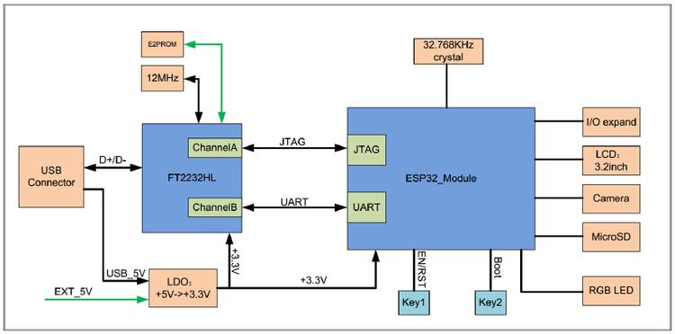
기능 설명
| 핵심 구성요소 | 설명 |
|---|---|
| FT2232 | USB로 program·control할 수 있는 multi-protocol USB-to-serial bridge입니다. Channel A는 USB-to-JTAG, channel B는 USB-to-serial을 제공해 ESP32 communication, application development와 debugging을 돕습니다. |
| 32.768kHz | Deep-sleep mode에서 low-power clock을 제공하는 external precision 32.768kHz crystal oscillator입니다. |
| 0R | Current shunt 자리의 zero-ohm resistor입니다. Desoldering하거나 shunt로 바꾸면 ESP32의 mode별 current consumption을 측정할 수 있습니다. |
| ESP32-WROVER-E module | Flexible extended storage와 data processing을 위한 64-Mbit PSRAM을 갖습니다. |
| Diagnostic LEDs | FT2232 GPIO에 연결된 red LED 4개로 future use를 위한 것입니다. |
| UART | FT2232와 ESP32의 serial TX/RX가 JP2 안쪽·바깥쪽으로 각각 나옵니다. Default jumper를 제거하면 ESP32 serial interface에 external serial device를 연결할 수 있습니다. |
| SPI | ESP32가 module 내부 flash와 PSRAM에 쓰는 SPI pin입니다. Extra CS signal을 사용하면 다른 3.3V SPI device도 연결할 수 있습니다. |
| CTS/RTS | Default로 회로와 연결되지 않은 serial flow-control signal입니다. JP14의 해당 pin을 jumper로 short하면 활성화됩니다. |
| JTAG | FT2232와 ESP32 JTAG signal이 JP2 안쪽·바깥쪽으로 나옵니다. Default는 disconnected이며 해당 pin을 jumper로 short해야 합니다. |
| USB Port | Board power와 computer-board communication을 제공하는 USB interface입니다. |
| EN Button | Reset button입니다. |
| BOOT Button | BOOT을 누른 채 EN을 누르면 serial firmware download mode를 시작합니다. |
| Power Switch | BOOT button 쪽으로 toggle하면 board가 켜지고 반대쪽이면 꺼집니다. |
| Power Selector | JP7 jumper로 USB 또는 5V Input을 power source로 선택합니다. |
| 5V input | 5.5×2.1mm center-positive standard coaxial connector용 5V power interface입니다. |
| 5V Power On LED | USB 또는 5V Input에서 power가 공급되면 켜지는 red LED입니다. |
| LDO | NCP1117 1A 5V-to-3.3V fixed-output LDO이며 adjustable-output LDO로 교체할 수도 있습니다. |
| Camera Connector | Standard OV7670 camera module interface입니다. |
| RGB LED | PWM으로 제어할 수 있는 red·green·blue LED입니다. |
| I/O Connector | ESP32 module pin을 header로 노출해 PWM, ADC, DAC, I2C, I2S, SPI 등을 사용할 수 있습니다. |
| MicroSD Card Slot | MicroSD card data storage와 retrieval application 개발에 사용합니다. |
| LCD | 3.2-inch 4-wire SPI LCD의 장착과 interface를 지원합니다. |
설정 선택지
Board 기능을 설정하는 jumper block 3개의 주요 조합은 다음과 같습니다.
| Header | Jumper setting | 기능 |
|---|---|---|
| JP7 | 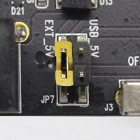 | External power supply로 board에 전원 공급 |
| JP7 | 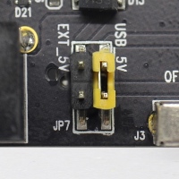 | USB로 board에 전원 공급 |
| JP2 | 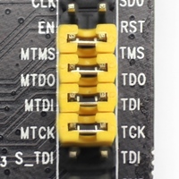 | JTAG 기능 활성화 |
| JP2 | 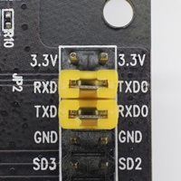 | UART communication 활성화 |
| JP14 | 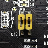 | Serial RTS/CTS flow control 활성화 |
ESP32 pin 할당
Onboard 또는 external hardware가 사용하지 않는 pin은 다른 용도로 쓸 수 있습니다. 그러나 GPIO0·GPIO2처럼 여러 기능을 갖거나 peripheral끼리 공유하는 pin이 있으므로 일부 조합은 함께 동작할 수 없습니다. 예를 들어 JTAG와 MicroSD가 여러 pin을 공유하므로 SD card를 사용하는 application은 JTAG debug할 수 없습니다.
LCD와 SD card는 GPIO21 하나만 공유합니다. LCD에서는 D/C signal, SD slot에서는 Card Detect입니다. Card Detect가 필요 없다면 R167을 제거해 LCD와 SD를 함께 사용할 수 있습니다.
Main I/O Connector / JP1
JP1은 14×2 male pin이며 양쪽 Shared With column은 각 GPIO가 board의 어디에서 함께 쓰이는지 나타냅니다.
| Shared With | I/O | I/O | Shared With |
|---|---|---|---|
| n/a | 3.3V | GND | n/a |
| NC/XTAL | IO32 | IO33 | NC/XTAL |
| JTAG, MicroSD | IO12 | IO13 | JTAG, MicroSD |
| JTAG, MicroSD | IO14 | IO27 | Camera |
| Camera | IO26 | IO25 | Camera, LCD |
| Camera | IO35 | IO34 | Camera |
| Camera | IO39 | IO36 | Camera |
| JTAG | EN | IO23 | Camera, LCD |
| Camera, LCD | IO22 | IO21 | Camera, LCD, MicroSD |
| Camera, LCD | IO19 | IO18 | Camera, LCD |
| Camera, LCD | IO5 | IO17 | PSRAM |
| PSRAM | IO16 | IO4 | LED, Camera, MicroSD |
| Camera, LED, Boot | IO0 | IO2 | LED, MicroSD |
| JTAG, MicroSD | IO15 | 5V |
Legend: NC/XTAL은 32.768kHz oscillator, JTAG는 JP2, Boot는 SW2, Camera는 JP4, LED는 RGB LED, MicroSD는 J4, LCD는 U5, PSRAM은 ESP32-WROVER-E PSRAM을 뜻합니다.
32.768kHz Oscillator
| No. | ESP32 Pin |
|---|---|
| 1 | GPIO32 |
| 2 | GPIO33 |
GPIO32와 GPIO33은 default로 oscillator에 연결되며 signal integrity를 위해 JP1에는 연결되지 않습니다. R11/R23의 zero-ohm resistor를 제거해 R12/R24로 옮기면 oscillator 대신 JP1에 할당할 수 있습니다.
SPI Flash / JP2
| No. | ESP32 Pin |
|---|---|
| 1 | CLK / GPIO6 |
| 2 | SD0 / GPIO7 |
| 3 | SD1 / GPIO8 |
| 4 | SD2 / GPIO9 |
| 5 | SD3 / GPIO10 |
| 6 | CDM / GPIO11 |
JTAG / JP2
| No. | ESP32 Pin | JTAG Signal |
|---|---|---|
| 1 | EN | TRST_N |
| 2 | MTMS / GPIO14 | TMS |
| 3 | MTDO / GPIO15 | TDO |
| 4 | MTDI / GPIO12 | TDI |
| 5 | MTCK / GPIO13 | TCK |
Camera / JP4
| No. | ESP32 Pin | Camera Signal |
|---|---|---|
| 1 | n/a | 3.3V |
| 2 | n/a | Ground |
| 3 | GPIO27 | SIO_C / SCCB Clock |
| 4 | GPIO26 | SIO_D / SCCB Data |
| 5 | GPIO25 | VSYNC / Vertical Sync |
| 6 | GPIO23 | HREF / Horizontal Reference |
| 7 | GPIO22 | PCLK / Pixel Clock |
| 8 | GPIO21 | XCLK / System Clock |
| 9 | GPIO35 | D7 / Pixel Data Bit 7 |
| 10 | GPIO34 | D6 / Pixel Data Bit 6 |
| 11 | GPIO39 | D5 / Pixel Data Bit 5 |
| 12 | GPIO36 | D4 / Pixel Data Bit 4 |
| 13 | GPIO19 | D3 / Pixel Data Bit 3 |
| 14 | GPIO18 | D2 / Pixel Data Bit 2 |
| 15 | GPIO5 | D1 / Pixel Data Bit 1 |
| 16 | GPIO4 | D0 / Pixel Data Bit 0 |
| 17 | GPIO0 | RESET / Camera Reset |
| 18 | n/a | PWDN / Camera Power Down |
D0~D7은 camera data bus입니다.
RGB LED
| No. | ESP32 Pin | RGB LED |
|---|---|---|
| 1 | GPIO0 | Red |
| 2 | GPIO2 | Green |
| 3 | GPIO4 | Blue |
MicroSD Card
| No. | ESP32 Pin | MicroSD Signal |
|---|---|---|
| 1 | MTDI / GPIO12 | DATA2 |
| 2 | MTCK / GPIO13 | CD / DATA3 |
| 3 | MTDO / GPIO15 | CMD |
| 4 | MTMS / GPIO14 | CLK |
| 5 | GPIO2 | DATA0 |
| 6 | GPIO4 | DATA1 |
| 7 | GPIO21 | Card Detect |
LCD / U5
| No. | ESP32 Pin | LCD Signal |
|---|---|---|
| 1 | GPIO18 | RESET |
| 2 | GPIO19 | SCL |
| 3 | GPIO21 | D/C |
| 4 | GPIO22 | CS |
| 5 | GPIO23 | SDA |
| 6 | GPIO25 | SDO |
| 7 | GPIO5 | Backlight |
Application 개발 시작
Power를 켜기 전에 board에 명백한 손상이 없는지 확인하십시오.
초기 설정
JP7에서 USB power source를 선택하고 JP2에서 UART communication만 활성화하십시오. 다른 jumper는 설치하지 않습니다. Power Switch를 ON으로 전환하면 5V Power On LED가 켜져야 합니다.
지원 기능
현재 Zephyr의 ESP32-Wrover-Kit board는 다음 interface와 driver를 지원합니다.
| Interface | Controller | Driver/Component |
|---|---|---|
| UART | on-chip | serial port |
| GPIO | on-chip | gpio |
| PINMUX | on-chip | pinmux |
| USB-JTAG | on-chip | hardware interface |
| SPI Master | on-chip | spi |
| Timers | on-chip | counter |
| Watchdog | on-chip | watchdog |
| TRNG | on-chip | entropy |
| LEDC | on-chip | pwm |
| MCPWM | on-chip | pwm |
| PCNT | on-chip | qdec |
| SPI DMA | on-chip | spi |
| TWAI | on-chip | can |
| ADC | on-chip | adc |
| DAC | on-chip | dac |
| Wi-Fi | on-chip | |
| Bluetooth | on-chip |
시스템 요구 사항
Espressif HAL에는 Wi-Fi와 Bluetooth binary blob이 필요합니다. west update 뒤 다음 명령을 실행하는 것이 좋습니다.
west blobs fetch hal_espressif빌드와 플래시
Simple boot
2nd-stage bootloader 없이 single binary image로 load하는 default 방식입니다. Security feature와 OTA update는 제공하지 않습니다.
MCUboot bootloader
MCUboot를 선택하면 bootloader를 적어도 한 번 build하고 flash해야 합니다. Sysbuild 또는 manual build를 사용할 수 있습니다.
CONFIG_BOOTLOADER_MCUBOOT=ySysbuild
ESP32 SoC bootstrap에 필요한 모든 image를 build·flash합니다.
west build --sysbuild -b esp_wrover_kit samples/hello_world기본적으로 MCUboot와 application image를 만들며 output은 domain subdirectory로 나뉩니다.
build/
├── hello_world
│   └── zephyr
│       ├── zephyr.elf
│       └── zephyr.bin
├── mcuboot
│    └── zephyr
│       ├── zephyr.elf
│       └── zephyr.bin
└── domains.yamlManual build
빠른 개발 iteration을 위해 image를 하나씩 build할 수 있습니다. MCUboot는 적어도 한 번 먼저 flash해야 합니다.
west build -b esp_wrover_kit/esp32/procpu samples/hello_world
west flash
Serial monitor는 다음과 같이 엽니다.
west espressif monitor***** Booting Zephyr OS vx.x.x-xxx-gxxxxxxxxxxxx *****
Hello World! esp_wrover_kit디버깅
ESP32 OpenOCD support는 version 0.12.0부터 upstream에 있습니다. OpenOCD를 설치하십시오.
ESP-WROVER-KIT의 JTAG pin은 console과 같은 device의 USB serial port에 내부 연결되어 있어 external hardware가 필요 없습니다. 다만 default로 disconnected인 JTAG signal jumper를 short해 internal controller에 연결해야 합니다. Header는 power switch에서 바라볼 때 board 오른쪽의 SPI·UART header 옆에 있습니다.
west build -b esp_wrover_kit/esp32/procpu samples/hello_world -- -DOPENOCD=<path/to/bin/openocd> -DOPENOCD_DEFAULT_PATH=<path/to/openocd/share/openocd/scripts>
west flash
west debug
관련 문서
Source
출처
영어 원문에는 문단, 문서 지시문, 표, 코드, 코드 심벌, 경로를 그대로 보존했습니다.