Part 1
요약·해설
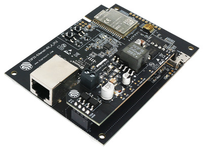
Ethernet board A는 ESP32-WROVER-E, IP101GRI 10/100 PHY와 FT2232H JTAG/serial bridge를 포함합니다. PoE board B는 IEEE 802.3at power를 5V·1.4A로 변환합니다.
10/100 Ethernet · Wi-Fi
PoE · 5V 1.4A
FT2232H · USB-JTAG
Part 2
접을 수 있는 영어 원문 전체
영어 원문 전체 펼치기
DC536E5DC101E6119DD7ABCB528A06E850449546B55107A169F7C0803CCC0384
.. _esp32_ethernet_kit:
ESP32-ETHERNET-KIT
##################
The ESP32-Ethernet-Kit is an Ethernet-to-Wi-Fi development board that enables
Ethernet devices to be interconnected over Wi-Fi. At the same time, to provide
more flexible power supply options, the ESP32-Ethernet-Kit also supports power
over Ethernet (PoE).
.. _get-started-esp32-ethernet-kit-v1.2-overview:
.. figure:: ../../../../../../../boards/espressif/esp32_ethernet_kit/doc/img/esp32-ethernet-kit-v1.2-overview.jpg
:align: center
:alt: ESP32-Ethernet-Kit V1.2
:figclass: align-center
ESP32-Ethernet-Kit V1.2 Overview
Overview
********
ESP32-Ethernet-Kit is an ESP32-based development board produced by
`Espressif <https://espressif.com>`_.
It consists of two development boards, the Ethernet board A and the PoE
board B. The `Ethernet board (A)`_ contains Bluetooth/Wi-Fi dual-mode
ESP32-WROVER-E module and IP101GRI, a Single Port 10/100 Fast Ethernet
Transceiver (PHY). The `PoE board (B)`_ provides power over Ethernet
functionality. The A board can work independently, without the board B
installed.
.. _get-started-esp32-ethernet-kit-v1.2:
.. figure:: ../../../../../../../boards/espressif/esp32_ethernet_kit/doc/img/esp32-ethernet-kit-v1.2.jpg
:align: center
:alt: ESP32-Ethernet-Kit V1.2
:figclass: align-center
ESP32-Ethernet-Kit V1.2
For the application loading and monitoring, the Ethernet board (A) also
features FTDI FT2232H chip - an advanced multi-interface USB bridge.
This chip enables to use JTAG for direct debugging of ESP32 through the
USB interface without a separate JTAG debugger.
Functionality Overview
======================
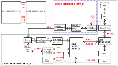
The block diagram below shows the main components of ESP32-Ethernet-Kit
and their interconnections.
.. figure:: ../../../../../../../boards/espressif/esp32_ethernet_kit/doc/img/esp32-ethernet-kit-v1.1-block-diagram.jpg
:align: center
:alt: ESP32-Ethernet-Kit block diagram
:figclass: align-center
ESP32-Ethernet-Kit block diagram
Functional Description
----------------------
The following figures and tables describe the key components, interfaces,
and controls of the ESP32-Ethernet-Kit.
.. _get-started-esp32-ethernet-kit-a-v1.2-layout:
Ethernet Board (A)
^^^^^^^^^^^^^^^^^^
.. figure:: ../../../../../../../boards/espressif/esp32_ethernet_kit/doc/img/esp32-ethernet-kit-a-v1.2-layout.jpg
:align: center
:alt: ESP32-Ethernet-Kit V1.2
:figclass: align-center
ESP32-Ethernet-Kit - Ethernet board (A) layout
The table below provides description starting from the picture's top right
corner and going clockwise.
.. list-table:: Table 1 Component Description
:widths: 40 150
:header-rows: 1
* - Key Component
- Description
* - ESP32-WROVER-E
- This ESP32 module features 64-Mbit PSRAM for flexible extended storage
and data processing capabilities.
* - GPIO Header 2
- Five unpopulated through-hole solder pads to provide access to selected
GPIOs of ESP32. For details, see `GPIO Header 2`_.
* - Function Switch
- A 4-bit DIP switch used to configure the functionality of selected GPIOs
of ESP32. For details see `Function Switch`_.
* - Tx/Rx LEDs
- Two LEDs to show the status of UART transmission.
* - FT2232H
- The FT2232H chip serves as a multi-protocol USB-to-serial bridge which
can be programmed and controlled via USB to provide communication with
ESP32. FT2232H also features USB-to-JTAG interface which is available
on channel A of the chip, while USB-to-serial is on channel B.
The FT2232H chip enhances user-friendliness in terms of application
development and debugging. See
`ESP32-Ethernet-Kit V1.2 Ethernet board (A) Schematic <https://dl.espressif.com/dl/schematics/SCH_ESP32-Ethernet-Kit_A_V1.2_20200528.pdf>`_.
* - USB Port
- USB interface. Power supply for the board as well as the communication
interface between a computer and the board.
* - Power Switch
- Power On/Off Switch. Toggling the switch to **5V0** position powers the
board on, toggling to **GND** position powers the board off.
* - 5V Input
- The 5 V power supply interface can be more convenient when the board is
operating autonomously (not connected to a computer).
* - 5V Power On LED
- This red LED turns on when power is supplied to the board, either from
USB or 5 V Input.
* - DC/DC Converter
- Provided DC 5 V to 3.3 V conversion, output current up to 2 A.
* - Board B Connectors
- A pair male and female header pins for mounting the `PoE board (B)`_
* - IP101GRI (PHY)
- The physical layer (PHY) connection to the Ethernet cable is
implemented using the
`IP101GRI <http://www.bdtic.com/DataSheet/ICplus/IP101G_DS_R01_20121224.pdf>`_
chip. The connection between PHY and ESP32 is done through the reduced
media-independent interface (RMII), a variant of the media-independent
interface `(MII) <https://en.wikipedia.org/wiki/Media-independent_interface>`_
standard. The PHY supports the IEEE 802.3/802.3u standard of 10/100
Mbps.
* - RJ45 Port
- Ethernet network data transmission port.
* - Magnetics Module
- The Magnetics are part of the Ethernet specification to protect against
faults and transients, including rejection of common mode signals
between the transceiver IC and the cable. The magnetics also provide
galvanic isolation between the transceiver and the Ethernet device.
* - Link/Activity LEDs
- Two LEDs (green and red) that respectively indicate the "Link" and
"Activity" statuses of the PHY.
* - BOOT Button
- Download button. Holding down **BOOT** and then pressing **EN**
initiates Firmware Download mode for downloading firmware through the
serial port.
* - EN Button
- Reset button.
* - GPIO Header 1
- This header provides six unpopulated through-hole solder pads connected
to spare GPIOs of ESP32. For details, see `GPIO Header 1`_.
PoE Board (B)
^^^^^^^^^^^^^
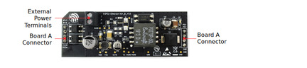
This board coverts power delivered over the Ethernet cable (PoE) to provide a
power supply for the Ethernet board (A). The main components of the PoE board
(B) are shown on the block diagram under `Functionality Overview`_.
The PoE board (B) has the following features:
* Support for IEEE 802.3at
* Power output: 5 V, 1.4 A
To take advantage of the PoE functionality the **RJ45 Port** of the Ethernet
board (A) should be connected with an Ethernet cable to a switch that supports
PoE. When the Ethernet board (A) detects 5 V power output from the PoE board
(B), the USB power will be automatically cut off.
.. figure:: ../../../../../../../boards/espressif/esp32_ethernet_kit/doc/img/esp32-ethernet-kit-b-v1.0-layout.jpg
:align: center
:alt: ESP32-Ethernet-Kit - PoE board (B)
:figclass: align-center
ESP32-Ethernet-Kit - PoE board (B) layout
.. list-table:: Table PoE board (B)
:widths: 40 150
:header-rows: 1
* - Key Component
- Description
* - Board A Connector
- Four female (left) and four male (right) header pins for connecting the
PoE board (B) to `Ethernet board (A)`_. The pins on the left accept
power coming from a PoE switch. The pins on the right deliver 5 V power
supply to the Ethernet board (A).
* - External Power Terminals
- Optional power supply (26.6 ~ 54 V) to the PoE board (B).
.. _get-started-esp32-ethernet-kit-v1.2-setup-options:
Setup Options
=============
This section describes options to configure the ESP32-Ethernet-Kit hardware.
Function Switch
---------------
When in On position, this DIP switch is routing listed GPIOs to FT2232H to
provide JTAG functionality. When in Off position, the GPIOs may be used for
other purposes.
======= ================
DIP SW GPIO Pin
======= ================
1 GPIO13
2 GPIO12
3 GPIO15
4 GPIO14
======= ================
RMII Clock Selection
--------------------
The ethernet MAC and PHY under RMII working mode need a common 50 MHz
reference clock (i.e. RMII clock) that can be provided either externally,
or generated from internal ESP32 APLL (not recommended).
.. note::
For additional information on the RMII clock selection, please refer to
`ESP32-Ethernet-Kit V1.2 Ethernet board (A) Schematic <https://dl.espressif.com/dl/schematics/SCH_ESP32-Ethernet-Kit_A_V1.2_20200528.pdf>`_,
sheet 2, location D2.
RMII Clock Sourced Externally by PHY
^^^^^^^^^^^^^^^^^^^^^^^^^^^^^^^^^^^^
By default, the ESP32-Ethernet-Kit is configured to provide RMII clock for the
IP101GRI PHY's 50M_CLKO output. The clock signal is generated by the frequency
multiplication of 25 MHz crystal connected to the PHY. For details, please see
the figure below.
.. figure:: ../../../../../../../boards/espressif/esp32_ethernet_kit/doc/img/esp32-ethernet-kit-rmii-clk-from-phy.jpg
:align: center
:alt: RMII Clock from IP101GRI PHY
:figclass: align-center
RMII Clock from IP101GRI PHY
Please note that the PHY is reset on power up by pulling the RESET_N signal
down with a resistor. ESP32 should assert RESET_N high with GPIO5 to enable
PHY. Only this can ensure the power-up of system. Otherwise ESP32 may enter
download mode (when the clock signal of REF_CLK_50M is at a high logic level
during the GPIO0 power-up sampling phase).
RMII Clock Sourced Internally from ESP32's APLL
^^^^^^^^^^^^^^^^^^^^^^^^^^^^^^^^^^^^^^^^^^^^^^^
Another option is to source the RMII Clock from internal ESP32 APLL, see
figure below. The clock signal coming from GPIO0 is first inverted, to account
for transmission line delay, and then supplied to the PHY.
.. figure:: ../../../../../../../boards/espressif/esp32_ethernet_kit/doc/img/esp32-ethernet-kit-rmii-clk-to-phy.jpg
:align: center
:alt: RMII Clock from ESP Internal APLL
:figclass: align-center
RMII Clock from ESP Internal APLL
To implement this option, users need to remove or add some RC components on
the board. For details please refer to
`ESP32-Ethernet-Kit V1.2 Ethernet board (A) Schematic <https://dl.espressif.com/dl/schematics/SCH_ESP32-Ethernet-Kit_A_V1.2_20200528.pdf>`_,
sheet 2, location D2. Please note that if the APLL is already used for other
purposes (e.g. I2S peripheral), then you have no choice but use an external
RMII clock.
GPIO Allocation
---------------
This section describes allocation of ESP32 GPIOs to specific interfaces or
functions of the ESP32-Ethernet-Kit.
IP101GRI (PHY) Interface
^^^^^^^^^^^^^^^^^^^^^^^^
The allocation of the ESP32 (MAC) pins to IP101GRI (PHY) is shown in the table
below. Implementation of ESP32-Ethernet-Kit defaults to Reduced
Media-Independent Interface (RMII).
==== ================ ===============
No. ESP32 Pin (MAC) IP101GRI (PHY)
==== ================ ===============
*RMII Interface*
---------------------------------------
1 GPIO21 TX_EN
2 GPIO19 TXD[0]
3 GPIO22 TXD[1]
4 GPIO25 RXD[0]
5 GPIO26 RXD[1]
6 GPIO27 CRS_DV
7 GPIO0 REF_CLK
---- ---------------- ---------------
*Serial Management Interface*
---------------------------------------
8 GPIO23 MDC
9 GPIO18 MDIO
---- ---------------- ---------------
*PHY Reset*
---------------------------------------
10 GPIO5 Reset_N
==== ================ ===============
.. note::
The allocation of all pins under the ESP32's *RMII Interface* is fixed and
cannot be changed either through IO MUX or GPIO Matrix. REF_CLK can only
be selected from GPIO0, GPIO16 or GPIO17 and it can not be changed through
GPIO Matrix.
GPIO Header 1
^^^^^^^^^^^^^
This header exposes some GPIOs that are not used elsewhere on the
ESP32-Ethernet-Kit.
==== ================
No. ESP32 Pin
==== ================
1 GPIO32
2 GPIO33
3 GPIO34
4 GPIO35
5 GPIO36
6 GPIO39
==== ================
GPIO Header 2
^^^^^^^^^^^^^
This header contains GPIOs that may be used for other purposes depending on
scenarios described in column "Comments".
==== ========== ====================
No. ESP32 Pin Comments
==== ========== ====================
1 GPIO17 See note 1
2 GPIO16 See note 1
3 GPIO4
4 GPIO2
5 GPIO13 See note 2
6 GPIO12 See note 2
7 GPIO15 See note 2
8 GPIO14 See note 2
9 GND Ground
10 3V3 3.3 V power supply
==== ========== ====================
.. note::
1. The ESP32 pins GPIO16 and GPIO17 are not broken out to the
ESP32-WROVER-E module and therefore not available for use. If you need
to use these pins, please solder a module without PSRAM memory inside,
e.g. the ESP32-WROOM-32D or ESP32-SOLO-1.
2. Functionality depends on the settings of the `Function Switch`_.
GPIO Allocation Summary
^^^^^^^^^^^^^^^^^^^^^^^
.. csv-table::
:header: ESP32-WROVER-E,IP101GRI,UART,JTAG,GPIO,Comments
S_VP,,,,IO36,
S_VN,,,,IO39,
IO34,,,,IO34,
IO35,,,,IO35,
IO32,,,,IO32,
IO33,,,,IO33,
IO25,RXD[0],,,,
IO26,RXD[1],,,,
IO27,CRS_DV,,,,
IO14,,,TMS,IO14,
IO12,,,TDI,IO12,
IO13,,,TCK,IO13,
IO15,,,TDO,IO15,
IO2,,,,IO2,
IO0,REF_CLK,,,,See note 1
IO4,,,,IO4,
IO16,,,,IO16 (NC),See note 2
IO17,,,,IO17 (NC),See note 2
IO5,Reset_N,,,,See note 1
IO18,MDIO,,,,
IO19,TXD[0],,,,
IO21,TX_EN,,,,
RXD0,,RXD,,,
TXD0,,TXD,,,
IO22,TXD[1],,,,
IO23,MDC,,,,
.. note::
1. To prevent the power-on state of the GPIO0 from being affected by the
clock output on the PHY side, the RESET_N signal to PHY defaults to
low, turning the clock output off. After power-on you can control
RESET_N with GPIO5 to turn the clock output on. See also
`RMII Clock Sourced Externally by PHY`_. For PHYs that cannot turn off
the clock output through RESET_N, it is recommended to use a crystal
module that can be disabled/enabled externally. Similarly like when
using RESET_N, the oscillator module should be disabled by default and
turned on by ESP32 after power-up. For a reference design please see
`ESP32-Ethernet-Kit V1.2 Ethernet board (A) Schematic <https://dl.espressif.com/dl/schematics/SCH_ESP32-Ethernet-Kit_A_V1.2_20200528.pdf>`_.
2. The ESP32 pins GPIO16 and GPIO17 are not broken out to the
ESP32-WROVER-E module and therefore not available for use. If you need
to use these pins, please solder a module without PSRAM memory inside,
e.g. the ESP32-WROOM-32D or ESP32-SOLO-1.
System requirements
*******************
Prerequisites
=============
Espressif HAL requires WiFi and Bluetooth binary blobs in order work. Run the command
below to retrieve those files.
.. code-block:: console
west blobs fetch hal_espressif
.. note::
It is recommended running the command above after :file:`west update`.
Building & Flashing
*******************
Simple boot
===========
The board could be loaded using the single binary image, without 2nd stage bootloader.
It is the default option when building the application without additional configuration.
.. note::
Simple boot does not provide any security features nor OTA updates.
MCUboot bootloader
==================
User may choose to use MCUboot bootloader instead. In that case the bootloader
must be build (and flash) at least once.
There are two options to be used when building an application:
1. Sysbuild
2. Manual build
.. note::
User can select the MCUboot bootloader by adding the following line
to the board default configuration file.
.. code:: cfg
CONFIG_BOOTLOADER_MCUBOOT=y
Sysbuild
========
The sysbuild makes possible to build and flash all necessary images needed to
bootstrap the board with the ESP32 SoC.
To build the sample application using sysbuild use the command:
.. zephyr-app-commands::
:tool: west
:app: samples/hello_world
:board: esp32_ethernet_kit
:goals: build
:west-args: --sysbuild
:compact:
By default, the ESP32 sysbuild creates bootloader (MCUboot) and application
images. But it can be configured to create other kind of images.
Build directory structure created by sysbuild is different from traditional
Zephyr build. Output is structured by the domain subdirectories:
.. code-block::
build/
├── hello_world
│   └── zephyr
│       ├── zephyr.elf
│       └── zephyr.bin
├── mcuboot
│    └── zephyr
│       ├── zephyr.elf
│       └── zephyr.bin
└── domains.yaml
.. note::
With ``--sysbuild`` option the bootloader will be re-build and re-flash
every time the pristine build is used.
For more information about the system build please read the :ref:`sysbuild` documentation.
Manual build
============
During the development cycle, it is intended to build & flash as quickly possible.
For that reason, images can be build one at a time using traditional build.
The instructions following are relevant for both manual build and sysbuild.
The only difference is the structure of the build directory.
.. note::
Remember that bootloader (MCUboot) needs to be flash at least once.
Build and flash applications as usual (see :ref:`build_an_application` and
:ref:`application_run` for more details).
.. zephyr-app-commands::
:zephyr-app: samples/hello_world
:board: esp32_ethernet_kit/esp32/procpu
:goals: build
The usual ``flash`` target will work with the ``esp32_ethernet_kit`` board
configuration. Here is an example for the :ref:`hello_world`
application.
.. zephyr-app-commands::
:zephyr-app: samples/hello_world
:board: esp32_ethernet_kit/esp32/procpu
:goals: flash
Open the serial monitor using the following command:
.. code-block:: shell
west espressif monitor
After the board has automatically reset and booted, you should see the following
message in the monitor:
.. code-block:: console
***** Booting Zephyr OS vx.x.x-xxx-gxxxxxxxxxxxx *****
Hello World! esp32_ethernet_kit
Debugging
*********
As with much custom hardware, the ESP32 modules require patches to
OpenOCD that are not upstreamed yet. Espressif maintains their own fork of
the project. The custom OpenOCD can be obtained at `OpenOCD ESP32`_
The Zephyr SDK uses a bundled version of OpenOCD by default. You can overwrite that behavior by adding the
``-DOPENOCD=<path/to/bin/openocd> -DOPENOCD_DEFAULT_PATH=<path/to/openocd/share/openocd/scripts>``
parameter when building.
Here is an example for building the :ref:`hello_world` application.
.. zephyr-app-commands::
:zephyr-app: samples/hello_world
:board: esp32_ethernet_kit/esp32/procpu
:goals: build flash
:gen-args: -DOPENOCD=<path/to/bin/openocd> -DOPENOCD_DEFAULT_PATH=<path/to/openocd/share/openocd/scripts>
You can debug an application in the usual way. Here is an example for the :ref:`hello_world` application.
.. zephyr-app-commands::
:zephyr-app: samples/hello_world
:board: esp32_ethernet_kit/esp32/procpu
:goals: debug
Enabling Ethernet
*****************
Enable Ethernet MAC, PHY and MDIO; add these to your device tree overlay:
.. code-block:: devicetree
ð {
status = "okay";
};
&phy {
status = "okay";
};
&mdio {
status = "okay";
};
Enable Ethernet in KConfig:
.. code-block:: cfg
CONFIG_ETH_ESP32=y
CONFIG_NETWORKING=y
CONFIG_NET_L2_ETHERNET=y
Board Init
==========
RESET_N (GPIO5) is automatically set high to enable the Ethernet PHY
during board initialization (board_init.c)
Related Documents
*****************
* `ESP32-Ethernet-Kit V1.2 Ethernet Board (A) Schematic <https://dl.espressif.com/dl/schematics/SCH_ESP32-Ethernet-Kit_A_V1.2_20200528.pdf>`_ (PDF)
* `ESP32-Ethernet-Kit PoE Board (B) Schematic <https://dl.espressif.com/dl/schematics/SCH_ESP32-ETHERNET-KIT_B_V1.0_20190517.pdf>`_ (PDF)
* `ESP32-Ethernet-Kit V1.2 Ethernet Board (A) PCB Layout <https://dl.espressif.com/dl/schematics/PCB_ESP32-Ethernet-Kit_A_V1_2_20190829.pdf>`_ (PDF)
* `ESP32-Ethernet-Kit PoE Board (B) PCB Layout <https://dl.espressif.com/dl/schematics/PCB_ESP32-Ethernet-Kit_B_V1_0_20190306.pdf>`_ (PDF)
* `ESP32 Datasheet <https://www.espressif.com/sites/default/files/documentation/esp32_datasheet_en.pdf>`_ (PDF)
* `ESP32-WROVER-E Datasheet <https://www.espressif.com/sites/default/files/documentation/esp32-wrover-e_esp32-wrover-ie_datasheet_en.pdf>`_ (PDF)
* `OpenOCD ESP32 <https://github.com/espressif/openocd-esp32/releases>`_
Part 3
한국어 전문 번역
소개
ESP32-Ethernet-Kit는 Ethernet device를 Wi-Fi로 서로 연결하는 Ethernet-to-Wi-Fi development board입니다. 전원 선택의 유연성을 높이기 위해 Power over Ethernet(PoE)도 지원합니다.
개요
ESP32-Ethernet-Kit는 Espressif가 생산한 ESP32 기반 development board입니다.
Ethernet board A와 PoE board B, 두 board로 구성됩니다. Ethernet board A에는 Bluetooth/Wi-Fi dual-mode ESP32-WROVER-E module과 single-port 10/100 Fast Ethernet transceiver인 IP101GRI PHY가 있습니다. PoE board B는 Power over Ethernet을 제공합니다. Board A는 board B 없이도 독립적으로 동작할 수 있습니다.
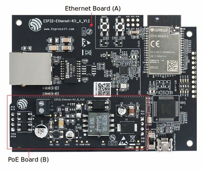
Application load와 monitoring을 위해 Ethernet board A에는 advanced multi-interface USB bridge인 FTDI FT2232H chip도 있습니다. 별도 JTAG debugger 없이 USB interface로 ESP32를 직접 JTAG debugging할 수 있습니다.
기능 개요
다음 block diagram은 주요 구성요소와 상호 연결을 보여줍니다.
Ethernet Board A
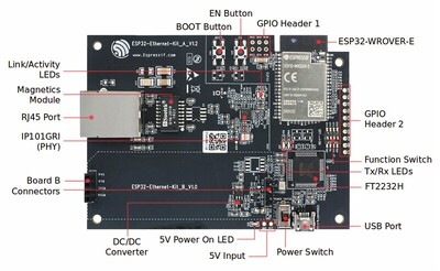
그림 오른쪽 위에서 시작해 시계 방향으로 본 핵심 구성요소는 다음과 같습니다.
| 핵심 구성요소 | 설명 |
|---|---|
| ESP32-WROVER-E | 유연한 확장 storage와 data processing을 위한 64-Mbit PSRAM을 갖춘 ESP32 module입니다. |
| GPIO Header 2 | 선택한 ESP32 GPIO에 접근하는, 부품이 장착되지 않은 through-hole solder pad 5개입니다. |
| Function Switch | 선택한 ESP32 GPIO의 기능을 구성하는 4-bit DIP switch입니다. |
| Tx/Rx LEDs | UART transmission 상태를 표시하는 LED 2개입니다. |
| FT2232H | USB로 program·control할 수 있는 multi-protocol USB-to-serial bridge입니다. Channel A는 USB-to-JTAG, channel B는 USB-to-serial을 제공해 application 개발과 debugging 편의성을 높입니다. |
| USB Port | Board 전원과 computer-board communication을 함께 제공하는 USB interface입니다. |
| Power Switch | 5V0 위치에서 board를 켜고 GND 위치에서 끕니다. |
| 5V Input | Computer에 연결하지 않고 자율 동작할 때 편리한 5V power supply interface입니다. |
| 5V Power On LED | USB 또는 5V Input으로 전원이 공급되면 켜지는 red LED입니다. |
| DC/DC Converter | DC 5V를 3.3V로 변환하며 최대 output current는 2A입니다. |
| Board B Connectors | PoE board B를 장착하는 male·female header pin 한 쌍입니다. |
| IP101GRI (PHY) | Ethernet cable의 physical layer를 구현합니다. ESP32와는 RMII로 연결되고 IEEE 802.3/802.3u 10/100Mbps를 지원합니다. |
| RJ45 Port | Ethernet network data transmission port입니다. |
| Magnetics Module | Fault·transient와 common-mode signal로부터 보호하고 transceiver와 Ethernet device 사이를 galvanic isolation합니다. |
| Link/Activity LEDs | PHY의 Link와 Activity 상태를 각각 표시하는 green·red LED입니다. |
| BOOT Button | BOOT를 누른 채 EN을 누르면 serial port firmware download mode가 시작됩니다. |
| EN Button | Reset button입니다. |
| GPIO Header 1 | 사용하지 않는 ESP32 GPIO에 연결된, 부품이 장착되지 않은 through-hole solder pad 6개입니다. |
PoE Board B
PoE board B는 Ethernet cable을 통해 전달된 power를 변환해 Ethernet board A에 전원을 공급합니다. IEEE 802.3at를 지원하며 output은 5V, 1.4A입니다.
PoE를 사용하려면 board A의 RJ45 Port를 PoE 지원 switch에 Ethernet cable로 연결합니다. Board A가 board B의 5V output을 감지하면 USB power는 자동으로 차단됩니다.
| 핵심 구성요소 | 설명 |
|---|---|
| Board A Connector | PoE board B를 Ethernet board A에 연결하는 female pin 4개(왼쪽)와 male pin 4개(오른쪽)입니다. 왼쪽은 PoE switch의 power를 받고 오른쪽은 board A에 5V를 전달합니다. |
| External Power Terminals | PoE board B에 26.6~54V optional power를 공급합니다. |
설정 선택지
Function Switch
DIP switch가 On이면 다음 GPIO를 FT2232H로 routing해 JTAG 기능을 제공합니다. Off이면 GPIO를 다른 목적으로 사용할 수 있습니다.
| DIP SW | GPIO Pin |
|---|---|
| 1 | GPIO13 |
| 2 | GPIO12 |
| 3 | GPIO15 |
| 4 | GPIO14 |
RMII Clock 선택
RMII mode에서 Ethernet MAC과 PHY는 공통 50MHz reference clock이 필요합니다. 외부에서 공급하거나 ESP32 내부 APLL에서 생성할 수 있지만 내부 APLL 방식은 권장하지 않습니다. 자세한 회로는 Ethernet board A schematic의 sheet 2, D2를 참조하십시오.
PHY가 외부에서 공급하는 RMII Clock
Default configuration에서는 IP101GRI PHY의 50M_CLKO output이 RMII clock을 제공합니다. PHY에 연결된 25MHz crystal의 frequency multiplication으로 생성됩니다.
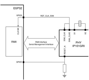
Power-up 때 resistor가 RESET_N을 low로 당겨 PHY를 reset합니다. ESP32가 GPIO5로 RESET_N을 high로 assert해야 PHY가 활성화되고 system이 정상적으로 켜집니다. 그렇지 않으면 GPIO0 power-up sampling 동안 REF_CLK_50M이 high일 때 ESP32가 download mode에 들어갈 수 있습니다.
ESP32 APLL 내부에서 공급하는 RMII Clock
다른 선택지는 ESP32 내부 APLL에서 RMII clock을 공급하는 것입니다. GPIO0의 clock signal은 transmission-line delay를 고려해 먼저 invert한 뒤 PHY로 전달합니다.
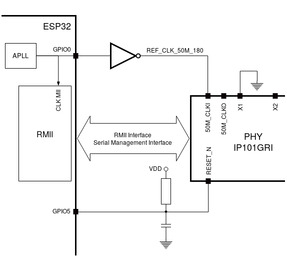
이 방식은 board의 일부 RC component를 제거하거나 추가해야 합니다. APLL을 I2S peripheral 같은 다른 용도로 이미 사용한다면 external RMII clock을 사용해야 합니다.
GPIO 할당
IP101GRI PHY Interface
ESP32 MAC과 IP101GRI PHY의 default connection은 Reduced Media-Independent Interface(RMII)입니다.
| No. | ESP32 Pin (MAC) | IP101GRI (PHY) |
|---|---|---|
| RMII 1 | GPIO21 | TX_EN |
| RMII 2 | GPIO19 | TXD[0] |
| RMII 3 | GPIO22 | TXD[1] |
| RMII 4 | GPIO25 | RXD[0] |
| RMII 5 | GPIO26 | RXD[1] |
| RMII 6 | GPIO27 | CRS_DV |
| RMII 7 | GPIO0 | REF_CLK |
| SMI 8 | GPIO23 | MDC |
| SMI 9 | GPIO18 | MDIO |
| PHY Reset 10 | GPIO5 | Reset_N |
GPIO Header 1
다른 곳에서 사용하지 않는 GPIO를 노출합니다.
| No. | ESP32 Pin |
|---|---|
| 1 | GPIO32 |
| 2 | GPIO33 |
| 3 | GPIO34 |
| 4 | GPIO35 |
| 5 | GPIO36 |
| 6 | GPIO39 |
GPIO Header 2
사용 시나리오에 따라 다른 목적으로 쓸 수 있는 GPIO입니다.
| No. | ESP32 Pin | Comments |
|---|---|---|
| 1 | GPIO17 | Note 1 |
| 2 | GPIO16 | Note 1 |
| 3 | GPIO4 | |
| 4 | GPIO2 | |
| 5 | GPIO13 | Note 2 |
| 6 | GPIO12 | Note 2 |
| 7 | GPIO15 | Note 2 |
| 8 | GPIO14 | Note 2 |
| 9 | GND | Ground |
| 10 | 3V3 | 3.3V power supply |
- GPIO16과 GPIO17은 ESP32-WROVER-E module 외부로 나오지 않아 사용할 수 없습니다. 필요하면 ESP32-WROOM-32D나 ESP32-SOLO-1처럼 PSRAM이 없는 module을 soldering하십시오.
- GPIO13·12·15·14의 기능은 Function Switch 설정에 따라 달라집니다.
GPIO 할당 요약
| ESP32-WROVER-E | IP101GRI | UART | JTAG | GPIO | Comments |
|---|---|---|---|---|---|
| S_VP | IO36 | ||||
| S_VN | IO39 | ||||
| IO34 | IO34 | ||||
| IO35 | IO35 | ||||
| IO32 | IO32 | ||||
| IO33 | IO33 | ||||
| IO25 | RXD[0] | ||||
| IO26 | RXD[1] | ||||
| IO27 | CRS_DV | ||||
| IO14 | TMS | IO14 | |||
| IO12 | TDI | IO12 | |||
| IO13 | TCK | IO13 | |||
| IO15 | TDO | IO15 | |||
| IO2 | IO2 | ||||
| IO0 | REF_CLK | Note 1 | |||
| IO4 | IO4 | ||||
| IO16 | IO16 (NC) | Note 2 | |||
| IO17 | IO17 (NC) | Note 2 | |||
| IO5 | Reset_N | Note 1 | |||
| IO18 | MDIO | ||||
| IO19 | TXD[0] | ||||
| IO21 | TX_EN | ||||
| RXD0 | RXD | ||||
| TXD0 | TXD | ||||
| IO22 | TXD[1] | ||||
| IO23 | MDC |
- PHY clock output이 GPIO0 power-on state에 영향을 주지 않도록 RESET_N은 default low여서 clock output을 끕니다. Power-up 후 GPIO5로 RESET_N을 제어해 clock을 켭니다. RESET_N으로 clock output을 끌 수 없는 PHY는 외부 enable/disable이 가능한 crystal module을 사용하고, default disabled 상태에서 ESP32가 power-up 후 켜는 방식을 권장합니다.
- GPIO16과 GPIO17은 ESP32-WROVER-E module에서 사용할 수 없습니다. 필요하면 PSRAM이 없는 module로 교체하십시오.
시스템 요구 사항
Espressif HAL에는 Wi-Fi와 Bluetooth binary blob이 필요합니다. west update 뒤 다음 명령을 실행하는 것이 좋습니다.
west blobs fetch hal_espressif빌드와 플래시
Simple boot
2nd-stage bootloader 없이 single binary image로 load하는 default 방식입니다. Security feature와 OTA update는 제공하지 않습니다.
MCUboot bootloader
MCUboot를 선택하면 bootloader를 적어도 한 번 build하고 flash해야 합니다. Sysbuild 또는 manual build를 사용할 수 있습니다.
CONFIG_BOOTLOADER_MCUBOOT=ySysbuild
Board bootstrap에 필요한 모든 image를 build·flash합니다.
west build --sysbuild -b esp32_ethernet_kit samples/hello_world기본적으로 MCUboot와 application image를 만들며, build output은 domain subdirectory로 나뉩니다.
build/
├── hello_world
│ └── zephyr
│ ├── zephyr.elf
│ └── zephyr.bin
├── mcuboot
│ └── zephyr
│ ├── zephyr.elf
│ └── zephyr.bin
└── domains.yamlManual build
개발 중에는 image를 하나씩 빠르게 build·flash할 수 있습니다. Sysbuild와 지침은 같고 build directory 구조만 다릅니다. MCUboot는 적어도 한 번 먼저 flash해야 합니다.
west build -b esp32_ethernet_kit/esp32/procpu samples/hello_world
west flash
Serial monitor는 다음과 같이 엽니다.
west espressif monitor***** Booting Zephyr OS vx.x.x-xxx-gxxxxxxxxxxxx *****
Hello World! esp32_ethernet_kit디버깅
ESP32 module에는 아직 upstream에 포함되지 않은 OpenOCD patch가 필요하며 Espressif가 자체 fork를 유지합니다. OpenOCD ESP32에서 받을 수 있습니다.
Zephyr SDK는 bundled OpenOCD를 기본 사용합니다. Build 때 다음 parameter로 custom binary와 script path를 지정할 수 있습니다.
-DOPENOCD=<path/to/bin/openocd> -DOPENOCD_DEFAULT_PATH=<path/to/openocd/share/openocd/scripts>west build -b esp32_ethernet_kit/esp32/procpu samples/hello_world -- -DOPENOCD=<path/to/bin/openocd> -DOPENOCD_DEFAULT_PATH=<path/to/openocd/share/openocd/scripts>
west flash
west debugEthernet 활성화
Device tree overlay에서 Ethernet MAC, PHY와 MDIO를 활성화합니다.
ð {
status = "okay";
};
&phy {
status = "okay";
};
&mdio {
status = "okay";
};Kconfig에서도 Ethernet을 활성화합니다.
CONFIG_ETH_ESP32=y
CONFIG_NETWORKING=y
CONFIG_NET_L2_ETHERNET=y
Board 초기화
board_init.c의 board initialization 과정에서 RESET_N(GPIO5)을 자동으로 high로 설정해 Ethernet PHY를 활성화합니다.
관련 문서
Source
출처
영어 원문에는 문단, 문서 지시문, 표, 코드, 코드 심벌, 경로를 그대로 보존했습니다.