Part 1
요약·해설
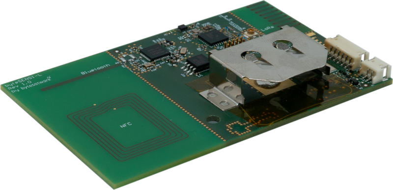
byteSENSI-L은 nRF52 MCU, Semtech LoRa radio와 여러 sensor를 통합합니다. 외부 전원·SWD·I2C·One Wire connector와 BLE·LoRa·GPS antenna connector를 제공합니다.
MCU
Nordic nRF52
Wireless
Bluetooth · Semtech LoRa
Programming
SEGGER J-Link · SWD
Part 2
접을 수 있는 영어 원문 전체
영어 원문 전체 펼치기
원문 SHA-256
1AC8C6F55F2738EB75D56F443D003E80DFDE5585C56EE76B4C8FBE2080583C5A
.. _bytesensi_l:

bytesatwork byteSENSI-L
#######################

Overview
********

The byteSENSI-L is a fun LoRa device based on nRF52 MCU that integrates many
sensors.

.. image:: ../../../../../../../boards/bytesatwork/bytesensi_l/doc/img/byteSENSI-L.jpg
   :width: 800px
   :align: center
   :alt: byteSENSI-L

Hardware
********

Supported Features
==================

+-----------+------------+----------------------+
| Interface | Controller | Driver/Component     |
+===========+============+======================+
| CLOCK     | on-chip    | clock_control        |
+-----------+------------+----------------------+
| FLASH     | on-chip    | flash                |
+-----------+------------+----------------------+
| GPIO      | on-chip    | gpio                 |
+-----------+------------+----------------------+
| I2C(M)    | on-chip    | i2c                  |
+-----------+------------+----------------------+
| MPU       | on-chip    | arch/arm             |
+-----------+------------+----------------------+
| NVIC      | on-chip    | arch/arm             |
+-----------+------------+----------------------+
| RADIO     | on-chip    | Bluetooth            |
+-----------+------------+----------------------+
| RADIO     | Semtech    | LoRa                 |
+-----------+------------+----------------------+
| RTC       | on-chip    | system clock         |
+-----------+------------+----------------------+
| RTT       | Segger     | console              |
+-----------+------------+----------------------+
| WDT       | on-chip    | watchdog             |
+-----------+------------+----------------------+

Connections and IOs
===================

External Connectors
-------------------

External Supply @ X1

+-------+--------------+---------------------------------------+
| PIN # | Signal Name  | Function                              |
+=======+==============+=======================================+
| 1     | VBAT         | Power input instead of CR2477 battery |
+-------+--------------+---------------------------------------+
| 2     | GND          | Ground                                |
+-------+--------------+---------------------------------------+

Programming Connector @ SL1

+-------+--------------+
| PIN # | Signal Name  |
+=======+==============+
| 1     | VBAT         |
+-------+--------------+
| 2     | SWDIO        |
+-------+--------------+
| 3     | GND          |
+-------+--------------+
| 4     | SWDCLK       |
+-------+--------------+
| 5     | GND          |
+-------+--------------+
| 6     | NC (SWO)     |
+-------+--------------+
| 7     | NC (Key)     |
+-------+--------------+
| 8     | NC           |
+-------+--------------+
| 9     | GND          |
+-------+--------------+
| 10    | nReset       |
+-------+--------------+

I2C Sensor @ X3

+-------+--------------+-------------------------+
| PIN # | Signal Name  | Function                |
+=======+==============+=========================+
| 1     | VBAT         | Power out               |
+-------+--------------+-------------------------+
| 2     | SCL          | I2C clock at P0.15      |
+-------+--------------+-------------------------+
| 3     | SDA          | I2C data at P0.16       |
+-------+--------------+-------------------------+
| 4     | INT          | Interrupt at P0.13      |
+-------+--------------+-------------------------+
| 5     | I2C_ADDR     | tied to VBAT            |
+-------+--------------+-------------------------+
| 6     | GND          | Ground                  |
+-------+--------------+-------------------------+

One Wire Sensor @ X2

+-------+----------------+-------------------------+
| PIN # | Signal Name    | Function                |
+=======+================+=========================+
| 1     | VDD            | 4V8                     |
+-------+----------------+-------------------------+
| 2     | IO             | One Wire                |
+-------+----------------+-------------------------+
| 3     | GND            | Ground                  |
+-------+----------------+-------------------------+

External BLE Antenna @ J1

External LoRa Antenna @ J2

External GPS Antenna @ J3

Programming and Debugging
*************************

Flashing
========
The byteSENSI-L board can be flashed with the SEGGER JLink programmer.

You can build and flash applications in the usual way. Here is an example for
the :ref:`hello_world` application.

   .. zephyr-app-commands::
      :zephyr-app: samples/hello_world
      :board: bytesensi_l
      :goals: build flash
      :compact:

Debugging
=========

Debugging your application can be done with ``west debug``.

Serial console
==============

The byteSENSI-L board only uses Segger's RTT console for providing serial
console. There is no physical serial port available.

References
**********
* `bytesatwork website <https://www.bytesatwork.io/>`_
* `bytesatwork wiki <https://wiki.bytesatwork.io/>`_
Part 3
한국어 전문 번역
개요
byteSENSI-L은 여러 sensor를 통합한 nRF52 MCU 기반의 재미있는 LoRa 장치입니다.
하드웨어
지원 기능
| Interface | Controller | Driver/Component |
|---|---|---|
| CLOCK | on-chip | clock_control |
| FLASH | on-chip | flash |
| GPIO | on-chip | gpio |
| I2C(M) | on-chip | i2c |
| MPU | on-chip | arch/arm |
| NVIC | on-chip | arch/arm |
| RADIO | on-chip | Bluetooth |
| RADIO | Semtech | LoRa |
| RTC | on-chip | system clock |
| RTT | Segger | console |
| WDT | on-chip | watchdog |
연결과 I/O
X1 외부 전원
| PIN # | Signal Name | Function |
|---|---|---|
| 1 | VBAT | CR2477 battery 대신 사용하는 전원 입력 |
| 2 | GND | Ground |
SL1 programming connector
| PIN # | Signal Name |
|---|---|
| 1 | VBAT |
| 2 | SWDIO |
| 3 | GND |
| 4 | SWDCLK |
| 5 | GND |
| 6 | NC (SWO) |
| 7 | NC (Key) |
| 8 | NC |
| 9 | GND |
| 10 | nReset |
X3 I2C sensor
| PIN # | Signal Name | Function |
|---|---|---|
| 1 | VBAT | 전원 출력 |
| 2 | SCL | P0.15의 I2C clock |
| 3 | SDA | P0.16의 I2C data |
| 4 | INT | P0.13의 interrupt |
| 5 | I2C_ADDR | VBAT에 연결됨 |
| 6 | GND | Ground |
X2 One Wire sensor
| PIN # | Signal Name | Function |
|---|---|---|
| 1 | VDD | 4V8 |
| 2 | IO | One Wire |
| 3 | GND | Ground |
J1은 외부 BLE antenna, J2는 외부 LoRa antenna, J3는 외부 GPS antenna connector입니다.
프로그래밍과 디버깅
Flashing
byteSENSI-L board는 SEGGER J-Link programmer로 flash할 수 있습니다.
일반적인 방법으로 application을 build하고 flash할 수 있습니다. 다음은 hello_world application 예입니다.
west build -b bytesensi_l samples/hello_world
west flash
Debugging
west debug로 application을 debug할 수 있습니다.
west debugSerial console
byteSENSI-L board는 serial console을 제공할 때 SEGGER RTT console만 사용합니다. 사용할 수 있는 물리 serial port는 없습니다.
참고 자료
Source
출처
영어 원문에는 문단, 문서 지시문, 표, 코드, 코드 심벌, 경로를 그대로 보존했습니다.