Part 1
요약·해설
Musca-S1은 FPU·DSP Cortex-M33, eMRAM 2 MB, QSPI 32 MB를 사용합니다. 일반 hello_world는 생성된 HEX를 바로 복사할 수 있고 TF-M sample은 CMake가 signed image를 자동 결합합니다.
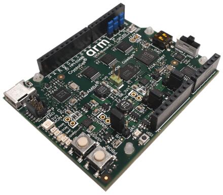
Cortex-M33 with FPU and DSP
512 KB SRAM · 2 MB eMRAM · 32 MB QSPI
CPU0 50 MHz · CPU1 up to 200 MHz
Part 2
접을 수 있는 영어 원문 전체
영어 원문 전체 펼치기
7D0431C3B12F25B82A63C2B5A6BB69ACBA133AAF4A046B32A42F3573359B2624
.. _v2m_musca_s1_board:

ARM V2M Musca-S1
################

Overview
********

The v2m_musca_s1 board configuration is used by Zephyr applications that run
on the V2M Musca-S1 board. It provides support for the Musca-S1 ARM Cortex-M33
CPU and the following devices:

- Nested Vectored Interrupt Controller (NVIC)
- System Tick System Clock (SYSTICK)
- Cortex-M System Design Kit GPIO
- Cortex-M System Design Kit UART

.. image:: ../../../../../../../boards/arm/v2m_musca_s1/doc/img/v2m_musca_s1.jpg
     :align: center
     :alt: ARM V2M Musca-S1

More information about the board can be found at the `V2M Musca-S1 Website`_.

Hardware
********

ARM V2M MUSCA-S1 provides the following hardware components:

- ARM Cortex-M33 (with FPU and DSP)
- ARM IoT Subsystem for Cortex-M33
- Memory

  - 512KB on-chip system memory SRAM.
  - 2MB on-chip eMRAM (non-volatile).
  - 32MB of external QSPI flash.

- Debug

  - JTAG, SWD & P-JTAG.
  - DAPLink with a virtual UART port.

- Arduino interface

  - 16 3V3 or 1V8 GPIO.
  - UART.
  - SPI.
  - I2C.
  - I2S.
  - 3-channel PWM.
  - 6-channel analog interface.

- On-board Peripherals

  - User RGB LED.
  - Gyro sensor.
  - Combined ADC/DAC/temperature sensor.


User push buttons
=================

The v2m_musca_s1 board provides the following user push buttons:

- PBON: power on/off.
- nSRST: Cortex-M33 system reset and CoreSight debug reset.
- ISP: Updates DAPLink firmware.


Supported Features
===================

The v2m_musca_s1 board configuration supports the following hardware features:

+-----------+------------+-------------------------------------+
| Interface | Controller | Driver/Component                    |
+===========+============+=====================================+
| NVIC      | on-chip    | nested vector interrupt controller  |
+-----------+------------+-------------------------------------+
| SYSTICK   | on-chip    | systick                             |
+-----------+------------+-------------------------------------+
| UART      | on-chip    | serial port-polling;                |
|           |            | serial port-interrupt               |
+-----------+------------+-------------------------------------+
| PINMUX    | on-chip    | pinmux                              |
+-----------+------------+-------------------------------------+
| GPIO      | on-chip    | gpio                                |
+-----------+------------+-------------------------------------+
| TIMER     | on-chip    | timer                               |
+-----------+------------+-------------------------------------+
| TrustZone | on-chip    | Trusted Firmware-M                  |
+-----------+------------+-------------------------------------+

Other hardware features are not currently supported by the port.
See the `V2M Musca-S1 Website`_ for a complete list of V2M Musca-S1 board
hardware features.

The default configuration can be found in the defconfig file:
:zephyr_file:`boards/arm/v2m_musca_s1/v2m_musca_s1_defconfig`.

Interrupt Controller
====================

Musca-S1 is a Cortex-M33 based SoC and has 15 fixed exceptions and 77 IRQs.

A Cortex-M33-based board uses vectored exceptions. This means each exception
calls a handler directly from the vector table.

Zephyr provides handlers for exceptions 1-7, 11, 12, 14, and 15, as listed
in the following table:

+------+------------+----------------+--------------------------+
| Exc# | Name       | Remarks        | Used by Zephyr Kernel    |
+======+============+================+==========================+
|  1   | Reset      |                | system initialization    |
+------+------------+----------------+--------------------------+
|  2   | NMI        |                | system fatal error       |
+------+------------+----------------+--------------------------+
|  3   | Hard fault |                | system fatal error       |
+------+------------+----------------+--------------------------+
|  4   | MemManage  | MPU fault      | system fatal error       |
+------+------------+----------------+--------------------------+
|  5   | Bus        |                | system fatal error       |
+------+------------+----------------+--------------------------+
|  6   | Usage      | Undefined      | system fatal error       |
|      | fault      | instruction,   |                          |
|      |            | or switch      |                          |
|      |            | attempt to ARM |                          |
|      |            | mode           |                          |
+------+------------+----------------+--------------------------+
|  7   | SecureFault| Unauthorized   | system fatal error       |
|      |            | access to      |                          |
|      |            | secure region  |                          |
|      |            | from ns space  |                          |
+------+------------+----------------+--------------------------+
|  8   | Reserved   |                | not handled              |
+------+------------+----------------+--------------------------+
|  9   | Reserved   |                | not handled              |
+------+------------+----------------+--------------------------+
| 10   | Reserved   |                | not handled              |
+------+------------+----------------+--------------------------+
| 11   | SVC        |                | system calls, kernel     |
|      |            |                | run-time exceptions,     |
|      |            |                | and IRQ offloading       |
+------+------------+----------------+--------------------------+
| 12   | Debug      |                | system fatal error       |
|      | monitor    |                |                          |
+------+------------+----------------+--------------------------+
| 13   | Reserved   |                | not handled              |
+------+------------+----------------+--------------------------+
| 14   | PendSV     |                | context switch           |
+------+------------+----------------+--------------------------+
| 15   | SYSTICK    |                | system clock             |
+------+------------+----------------+--------------------------+
| 16   | Reserved   |                | not handled              |
+------+------------+----------------+--------------------------+
| 17   | Reserved   |                | not handled              |
+------+------------+----------------+--------------------------+
| 18   | Reserved   |                | not handled              |
+------+------------+----------------+--------------------------+

Pin Mapping
===========

The ARM V2M Musca-S1 board's GPIO controller is responsible for pin-muxing,
input/output, pull-up, etc.
All GPIO controller pins are exposed via pins 0 - 15.

Mapping from the ARM V2M Musca-S1 Board pins to GPIO controller pins:

.. rst-class:: rst-columns

   - D0 : P0_0
   - D1 : P0_1
   - D2 : P0_2
   - D3 : P0_3
   - D4 : P0_4
   - D5 : P0_5
   - D6 : P0_6
   - D7 : P0_7
   - D8 : P0_8
   - D9 : P0_9
   - D10 : P0_10
   - D11 : P0_11
   - D12 : P0_12
   - D13 : P0_13
   - D14 : P0_14
   - D15 : P0_15

Peripheral Mapping:

.. rst-class:: rst-columns

   - UART_0_RX : D0
   - UART_0_TX : D1
   - SPI_0_CS : D10
   - SPI_0_MOSI : D11
   - SPI_0_MISO : D12
   - SPI_0_SCLK : D13
   - I2C_0_SDA : D14
   - I2C_0_SCL : D15

For more details please refer to `Musca-S1 Technical Reference Manual (TRM)`_.


RGB LED
============

Musca-S1 has a built-in RGB LED connected to GPIO[4:2] pins.

- Red LED connected at GPIO[2] pin,with optional PWM0.
- Green LED connected at GPIO[3] pin,with optional PWM1.
- Blue LED connected at GPIO[4] pin,with optional PWM2.

.. note:: The SCC registers select the functions of pins GPIO[4:2].

System Clock
============

V2M Musca-S1 has a 32.768kHz crystal clock. The clock goes to a PLL and is
multiplied to drive the Cortex-M33 processors and SSE-200 subsystem. The
default is 50MHz but can be increased to 200MHz maximum for the secondary
processor (CPU1) via software configuration. The maximum clock frequency
for the primary processor (CPU0) is 50MHz.

Serial Port
===========

The ARM Musca-S1 processor has two UARTs. Both the UARTs have only two wires
for RX/TX and no flow control (CTS/RTS) or FIFO. The Zephyr console output,
by default, uses UART1.

Security components
===================

- Implementation Defined Attribution Unit (`IDAU`_). The IDAU is used to define
  secure and non-secure memory maps. By default, all of the memory space is
  defined to be secure accessible only.
- Secure and Non-secure peripherals via the Peripheral Protection Controller
  (PPC). Peripherals can be assigned as secure or non-secure accessible.
- Secure boot.
- Secure `AMBA®`_ interconnect.

Serial Configuration Controller (SCC)
=====================================

The ARM Musca-S1 test chip implements a Serial Configuration Control (SCC)
register. The purpose of this register is to allow individual control of
clocks, reset-signals and interrupts to peripherals, and pin-muxing.

Boot memory
================
Normal Musca-S1 test chip boot operation is from 2MB eMRAM by default, and
it offers the fastest boot method. Musca-S1 test chip also support to boot from
32MB off-chip QSPI flash. You can update the DAPLink firmware and set the boot
selector slider switch for either QSPI or eMRAM for booting.

Programming and Debugging
*************************

Musca-S1 supports the v8m security extension, and by default boots to the
secure state.

When building a secure/non-secure application, the secure application will
have to set the IDAU/SAU and MPC configuration to permit access from the
non-secure application before jumping.

The following system components are required to be properly configured during
the secure firmware:

- AHB5 TrustZone Memory Protection Controller (MPC).
- AHB5 TrustZone Peripheral Protection Controller (PPC).
- Implementation-Defined Attribution Unit (IDAU).

For more details please refer to `Corelink SSE-200 Subsystem`_.

Flashing
========

DAPLink
---------

V2M Musca-S1 provides:

- A USB connection to the host computer, which exposes a Mass Storage and an
  USB Serial Port.
- A Serial Flash device, which implements the USB flash disk file storage.
- A physical UART connection which is relayed over interface USB Serial port.

This interfaces are exposed via DAPLink which provides:

- Serial Wire Debug (SWD).
- USB Mass Storage Device (USBMSD).
- UART.
- Remote reset.

For more details please refer
to the `DAPLink Website`_.


Building a secure only application
----------------------------------

You can build applications in the usual way. Here is an example for
the :ref:`hello_world` application.

.. zephyr-app-commands::
   :zephyr-app: samples/hello_world
   :board: v2m_musca_s1
   :goals: build

Open a serial terminal (minicom, putty, etc.) with the following settings:

- Speed: 115200
- Data: 8 bits
- Parity: None
- Stop bits: 1

Uploading an application to V2M Musca-S1
----------------------------------------

To upload the :ref:`hello_world` application to the board, no extra steps are
required. You can directly upload ``build/zephyr/zephyr.hex``, which is
generated by Zephyr's build system.

In other situations, applications must first be converted to Intel's hex
format before being flashed to a V2M Musca-S1. An optional bootloader can also
be prepended to the image.

The eMRAM base address alias is ``0xA000000``, and the QSPI flash base address
alias is ``0x0``. The image offset is calculated by adding the flash offset to the
bootloader partition size (when there is one).

A third-party tool (srecord) can be used to concatenate the images and generate
the Intel formatted hex image.

For more information refer to the `Srecord Manual`_.

.. code-block:: bash

   srec_cat $BIN_BOOTLOADER -Binary -offset $FLASH_OFFSET $BIN_APP -Binary -offset $IMAGE_OFFSET -o zephyr.hex -Intel

   # For a 128K bootloader IMAGE_OFFSET = $FLASH_OFFSET + 0x20000
   srec_cat $BIN_BOOTLOADER -Binary -offset 0xA000000 $BIN_APP -Binary -offset 0xA020000 -o zephyr.hex -Intel

.. image:: ../../../../../../../boards/arm/v2m_musca_s1/doc/img/v2m_musca_s1_powered.jpg
     :align: center
     :alt: The Musca-S1 with the USB connected and powered-on

To upload the application, connect the V2M Musca-S1 to your host computer using
the USB port and power-on the board by pressing the PBON button as seen on the
picture above. The 3 LEDs should be lit (PWR, ON and 5VON) and you should see a
USB connection exposing a Mass Storage (MUSCA_S) and a USB Serial Port.
Now copy the generated ``zephyr.hex`` to the MUSCA_S drive.

Reset the board, and if you were building the hello_world application you should
see the following message on the corresponding serial port:

.. code-block:: console

   Musca-S1 Dual Firmware Version 1.9
   *** Booting Zephyr OS build zephyr-v2.4.0-2314-gadc81d188323  ***
   Hello World! musca_s1

Building a secure/non-secure image with Trusted Firmware-M
----------------------------------------------------------

The process requires five steps:

1. Build Trusted Firmware-M (TF-M).
2. Import it as a library to the Zephyr source folder.
3. Build Zephyr with a non-secure configuration.
4. Merge the two binaries together and sign them.
5. Concatenate the bootloader with the signed image blob.

In order to build tfm please refer to `Trusted Firmware-M Guide`_.
Follow the build steps for AN521 target while replacing the platform with
``-DTFM_PLATFORM=musca_s1`` and compiler (if required) with
``-DTFM_TOOLCHAIN_FILE=toolchain_GNUARM.cmake``.

Copy over TF-M as a library to the Zephyr project source and create a shortcut
for the secure veneers and necessary header files. All files are in the install
folder after TF-M built.

Building the TF-M integration sample for Musca-S1
-------------------------------------------------

The TF-M integration samples can be run using the ``v2m_musca_s1/musca_s1/ns``
target. Please make sure all the requirements listed in the sample's
description are met before building.

.. zephyr-app-commands::
   :zephyr-app: samples/tfm_integration/psa_crypto
   :board: v2m_musca_s1/musca_s1/ns
   :goals: build

To upload the build artifact to the board, first connect the Musca-S1 to your
computer using the USB port, press the PBON button, and copy
the ``build/tfm_zephyr.hex`` file onto the MUSCA_S mass storage device.
(For a more detailed description of these steps, please read the 'Uploading
an application to V2M Musca-S1' section.)

Once the file transfer has completed, you may reset the board.

The ``tfm_zephyr.hex`` file was generated by concatenating the signed TF-M and
Zephyr binaries with the MCUboot image, and converting it to Intel's hex format.
These steps are all performed automatically by CMake.

For alternative build options and more information, please read the
corresponding TF-M integration example's README file.

.. _V2M Musca-S1 Website:
   https://developer.arm.com/Tools%20and%20Software/Musca-S1%20Test%20Chip%20Board

.. _Musca-S1 Technical Reference Manual (TRM):
   https://developer.arm.com/documentation/101835/latest

.. _DAPLink Website:
   https://github.com/ARMmbed/DAPLink

.. _Cortex-M33 Generic User Guide:
   https://developer.arm.com/documentation/100235/latest/

.. _Trusted Firmware-M Guide:
   https://tf-m-user-guide.trustedfirmware.org/building/tfm_build_instruction.html

.. _Corelink SSE-200 Subsystem:
   https://developer.arm.com/documentation/dto0051/latest/subsystem-overview/about-the-sse-200

.. _Srecord Manual:
   https://srecord.sourceforge.net/man/man1/srec_cat.1.html

.. _IDAU:
   https://developer.arm.com/documentation/100690/latest/Attribution-units--SAU-and-IDAU-

.. _AMBA®:
   https://developer.arm.com/architectures/system-architectures/amba
Part 3
한국어 전문 번역
개요
v2m_musca_s1 보드 구성은 Musca-S1에서 실행하는 Zephyr application용입니다. Arm Cortex-M33, NVIC, SYSTICK, CMSDK GPIO·UART를 지원합니다.
하드웨어
- FPU와 DSP를 포함한 Arm Cortex-M33, Cortex-M33용 Arm IoT Subsystem
- memory: on-chip SRAM 512 KB, non-volatile on-chip eMRAM 2 MB, external QSPI flash 32 MB
- debug: JTAG, SWD, P-JTAG, virtual UART가 있는 DAPLink
- Arduino interface: 3.3 V 또는 1.8 V GPIO 16개, UART, SPI, I2C, I2S, 3-channel PWM, 6-channel analog
- on-board: user RGB LED, gyro sensor, ADC/DAC/temperature 복합 sensor
User push button
PBON: power on/offnSRST: Cortex-M33 system reset와 CoreSight debug resetISP: DAPLink firmware update
지원 기능
| Interface | Controller | Driver/Component |
|---|---|---|
| NVIC | on-chip | nested vector interrupt controller |
| SYSTICK | on-chip | systick |
| UART | on-chip | serial port-polling; serial port-interrupt |
| PINMUX | on-chip | pinmux |
| GPIO | on-chip | gpio |
| TIMER | on-chip | timer |
| TrustZone | on-chip | Trusted Firmware-M |
그 밖의 hardware는 현재 port에서 지원하지 않습니다. 기본 구성은 boards/arm/v2m_musca_s1/v2m_musca_s1_defconfig입니다.
Interrupt controller
Musca-S1은 Cortex-M33 기반 SoC로 15개의 fixed exception과 77개의 IRQ가 있습니다. vectored exception을 사용하므로 각 exception이 vector table의 handler를 직접 호출합니다. Zephyr는 exception 1~7, 11, 12, 14, 15에 handler를 제공합니다.
| Exc# | Name | Remarks | Zephyr kernel 용도 |
|---|---|---|---|
| 1 | Reset | system initialization | |
| 2 | NMI | system fatal error | |
| 3 | Hard fault | system fatal error | |
| 4 | MemManage | MPU fault | system fatal error |
| 5 | Bus | system fatal error | |
| 6 | Usage fault | undefined instruction 또는 ARM mode 전환 시도 | system fatal error |
| 7 | SecureFault | non-secure space에서 secure region 무단 접근 | system fatal error |
| 8 | Reserved | not handled | |
| 9 | Reserved | not handled | |
| 10 | Reserved | not handled | |
| 11 | SVC | system calls, kernel run-time exceptions, IRQ offloading | |
| 12 | Debug monitor | system fatal error | |
| 13 | Reserved | not handled | |
| 14 | PendSV | context switch | |
| 15 | SYSTICK | system clock | |
| 16 | Reserved | not handled | |
| 17 | Reserved | not handled | |
| 18 | Reserved | not handled |
Pin mapping
GPIO controller가 pin muxing, input/output, pull-up 등을 담당하며 GPIO pin 0~15가 노출됩니다.
| Board pin | GPIO pin |
|---|---|
| D0 | P0_0 |
| D1 | P0_1 |
| D2 | P0_2 |
| D3 | P0_3 |
| D4 | P0_4 |
| D5 | P0_5 |
| D6 | P0_6 |
| D7 | P0_7 |
| D8 | P0_8 |
| D9 | P0_9 |
| D10 | P0_10 |
| D11 | P0_11 |
| D12 | P0_12 |
| D13 | P0_13 |
| D14 | P0_14 |
| D15 | P0_15 |
Peripheral mapping
| Peripheral signal | Digital pin |
|---|---|
| UART_0_RX | D0 |
| UART_0_TX | D1 |
| SPI_0_CS | D10 |
| SPI_0_MOSI | D11 |
| SPI_0_MISO | D12 |
| SPI_0_SCLK | D13 |
| I2C_0_SDA | D14 |
| I2C_0_SCL | D15 |
자세한 내용은 Musca-S1 Technical Reference Manual(TRM)을 참고합니다.
RGB LED
Musca-S1의 built-in RGB LED는 GPIO[4:2]에 연결됩니다.
- Red: GPIO[2], optional PWM0
- Green: GPIO[3], optional PWM1
- Blue: GPIO[4], optional PWM2
SCC register가 GPIO[4:2] pin function을 선택합니다.
System clock
32.768 kHz crystal clock을 PLL에서 배수해 Cortex-M33 processor와 SSE-200 subsystem을 구동합니다. 기본은 50 MHz이며 secondary processor CPU1은 software 설정으로 최대 200 MHz, primary processor CPU0은 최대 50 MHz입니다.
Serial port
UART는 2개입니다. RX/TX 두 선만 사용하고 CTS/RTS flow control과 FIFO는 없습니다. 기본 Zephyr console은 UART1입니다.
Security component
- IDAU가 secure/non-secure memory map을 정의합니다. 기본적으로 전체 memory space는 secure-only입니다.
- PPC로 peripheral을 secure 또는 non-secure access로 배정합니다.
- Secure boot와 Secure AMBA interconnect를 제공합니다.
Serial Configuration Controller
Musca-S1 test chip의 SCC register는 peripheral clock, reset signal, interrupt와 pin muxing을 개별 제어합니다.
Boot memory
기본 boot는 가장 빠른 2 MB eMRAM에서 수행합니다. 32 MB off-chip QSPI에서도 boot할 수 있습니다. DAPLink firmware를 갱신하고 boot selector slider switch를 QSPI 또는 eMRAM에 맞춰 설정합니다.
프로그래밍과 디버깅
Musca-S1은 Armv8-M Security Extension을 지원하며 기본적으로 Secure state로 boot합니다. Secure/Non-Secure application에서는 Secure application이 jump하기 전에 Non-Secure access를 허용하도록 IDAU/SAU와 MPC를 설정해야 합니다. Secure firmware에서 AHB5 TrustZone MPC, AHB5 TrustZone PPC, IDAU를 올바르게 구성해야 합니다.
Flashing
DAPLink
USB 연결은 host에 Mass Storage와 USB Serial Port를 노출합니다. Serial Flash가 USB flash disk storage를 구현하며 physical UART는 USB Serial Port로 relay됩니다. DAPLink는 다음 interface를 제공합니다.
- Serial Wire Debug(SWD)
- USB Mass Storage Device(USBMSD)
- UART
- remote reset
Secure-only application build
west build -b v2m_musca_s1 samples/hello_worldterminal은 115200 baud, 8 data bit, parity none, 1 stop bit로 엽니다.
Application upload
hello_world는 Zephyr build system이 만든 build/zephyr/zephyr.hex를 바로 upload할 수 있습니다. 다른 경우에는 Intel HEX로 변환해야 하며 optional bootloader를 앞에 붙일 수 있습니다. eMRAM base alias는 0xA000000, QSPI flash base alias는 0x0입니다. bootloader가 있으면 image offset은 flash offset과 bootloader partition size의 합입니다.
srec_cat $BIN_BOOTLOADER -Binary -offset $FLASH_OFFSET $BIN_APP -Binary -offset $IMAGE_OFFSET -o zephyr.hex -Intel

# 128K bootloader: IMAGE_OFFSET = $FLASH_OFFSET + 0x20000
srec_cat $BIN_BOOTLOADER -Binary -offset 0xA000000 $BIN_APP -Binary -offset 0xA020000 -o zephyr.hex -Intel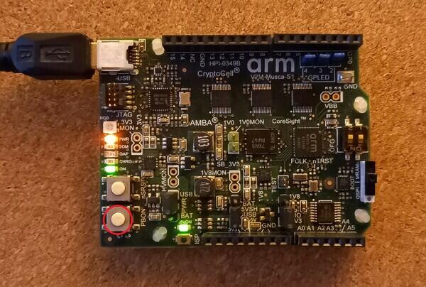
USB를 연결하고 PBON을 누릅니다. PWR, ON, 5VON LED 3개가 켜지고 MUSCA_S Mass Storage와 USB Serial Port가 나타나야 합니다. 생성된 zephyr.hex를 MUSCA_S drive에 복사하고 reset합니다.
Musca-S1 Dual Firmware Version 1.9
*** Booting Zephyr OS build zephyr-v2.4.0-2314-gadc81d188323  ***
Hello World! musca_s1
Trusted Firmware-M으로 Secure/Non-Secure image build
- TF-M을 build합니다.
- Zephyr source folder에 library로 import합니다.
- Non-Secure configuration으로 Zephyr를 build합니다.
- 두 binary를 병합하고 sign합니다.
- bootloader와 signed image blob을 concatenate합니다.
TF-M Guide의 AN521 절차에서 platform은 -DTFM_PLATFORM=musca_s1, 필요 시 toolchain은 -DTFM_TOOLCHAIN_FILE=toolchain_GNUARM.cmake로 바꿉니다. TF-M install folder의 secure veneer와 header file을 Zephyr project에 연결합니다.
TF-M integration sample
v2m_musca_s1/musca_s1/ns target으로 TF-M integration sample을 실행할 수 있습니다. sample 설명의 요구 조건을 먼저 충족해야 합니다.
west build -b v2m_musca_s1/musca_s1/ns samples/tfm_integration/psa_cryptoUSB를 연결하고 PBON을 누른 뒤 build/tfm_zephyr.hex를 MUSCA_S에 복사하고 reset합니다. 이 파일은 signed TF-M·Zephyr binary와 MCUboot image를 concatenate하고 Intel HEX로 변환한 결과이며 CMake가 전 과정을 자동 수행합니다. 다른 build option은 해당 TF-M integration example README를 참고합니다.
참고 자료
Source
출처
영어 원문에는 문단, 문서 지시문, 표, 코드, 코드 심벌, 경로를 그대로 보존했습니다.