Part 1
요약·해설
V2M Beetle은 Cortex-M3, CORDIO Bluetooth Smart radio, embedded/external flash와 Arduino interface를 제공합니다. Zephyr console은 UART1입니다.
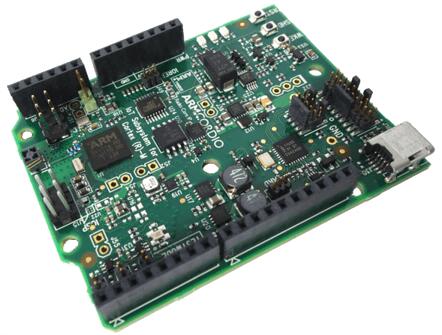
Arm Cortex-M3
256 KB flash · 128 KB SRAM · 2 MB QSPI
32.768 kHz slow · 24 MHz main
Part 2
접을 수 있는 영어 원문 전체
영어 원문 전체 펼치기
E1F0402D2AF332C67D6EB6A871386B6264D9F4B39BAF6DB72DF669CB8293FD23
.. _v2m_beetle_board:

ARM V2M Beetle
##############

Overview
********

The v2m_beetle board configuration is used by Zephyr applications that run on
the V2M Beetle board. It provides support for the Beetle ARM Cortex-M3 CPU and
the following devices:

- Nested Vectored Interrupt Controller (NVIC)
- System Tick System Clock (SYSTICK)
- Cortex-M System Design Kit GPIO
- Cortex-M System Design Kit UART

.. image:: ../../../../../../../boards/arm/v2m_beetle/doc/img/v2m_beetle.jpg
     :align: center
     :alt: ARM V2M Beetle

More information about the board can be found at the `V2M Beetle Website`_.

Hardware
********

ARM V2M BEETLE provides the following hardware components:

- ARM Cortex-M3
- ARM IoT Subsystem for Cortex-M
- CORDIO Bluetooth Smart radio
- Memory

  - 256KB of embedded flash
  - 128KB SRAM
  - 2MB of external QSPI flash.

- Debug

  - JTAG, SWD & 4 bit TRACE
  - CMSIS-DAP with a virtual UART port

- Arduino interface

  - GPIO, UART, SPI, I2C
  - Analog signals


Supported Features
===================

The v2m_beetle board configuration supports the following hardware features:

+-----------+------------+-------------------------------------+
| Interface | Controller | Driver/Component                    |
+===========+============+=====================================+
| NVIC      | on-chip    | nested vector interrupt controller  |
+-----------+------------+-------------------------------------+
| SYSTICK   | on-chip    | systick                             |
+-----------+------------+-------------------------------------+
| UART      | on-chip    | serial port-polling;                |
|           |            | serial port-interrupt               |
+-----------+------------+-------------------------------------+
| PINMUX    | on-chip    | pinmux                              |
+-----------+------------+-------------------------------------+
| GPIO      | on-chip    | gpio                                |
+-----------+------------+-------------------------------------+
| WATCHDOG  | on-chip    | watchdog                            |
+-----------+------------+-------------------------------------+
| TIMER     | on-chip    | timer                               |
+-----------+------------+-------------------------------------+

Other hardware features are not currently supported by the port.
See the `V2M Beetle Website`_ for a complete list of V2M Beetle board hardware
features.

The default configuration can be found in the defconfig file:

.. code-block:: console

   boards/arm/v2m_beetle/v2m_beetle_defconfig

Interrupt Controller
====================

Beetle is a Cortex-M3 based SoC and has 15 fixed exceptions and 45 IRQs.

A Cortex-M3/4-based board uses vectored exceptions. This means each exception
calls a handler directly from the vector table.

Handlers are provided for exceptions 1-6, 11-12, and 14-15. The table here
identifies the handlers used for each exception.

+------+------------+----------------+--------------------------+
| Exc# | Name       | Remarks        | Used by Zephyr Kernel    |
+======+============+================+==========================+
| 1    | Reset      |                | system initialization    |
+------+------------+----------------+--------------------------+
| 2    | NMI        |                | system fatal error       |
+------+------------+----------------+--------------------------+
| 3    | Hard fault |                | system fatal error       |
+------+------------+----------------+--------------------------+
| 4    | MemManage  | MPU fault      | system fatal error       |
+------+------------+----------------+--------------------------+
| 5    | Bus        |                | system fatal error       |
+------+------------+----------------+--------------------------+
| 6    | Usage      | undefined      | system fatal error       |
|      | fault      | instruction,   |                          |
|      |            | or switch      |                          |
|      |            | attempt to ARM |                          |
|      |            | mode           |                          |
+------+------------+----------------+--------------------------+
| 11   | SVC        |                | system calls, kernel     |
|      |            |                | run-time exceptions,     |
|      |            |                | and IRQ offloading       |
+------+------------+----------------+--------------------------+
| 12   | Debug      |                | system fatal error       |
|      | monitor    |                |                          |
+------+------------+----------------+--------------------------+
| 14   | PendSV     |                | context switch           |
+------+------------+----------------+--------------------------+
| 15   | SYSTICK    |                | system clock             |
+------+------------+----------------+--------------------------+

Pin Mapping
===========

The ARM V2M Beetle Board has 4 GPIO controllers. These controllers are responsible for pin muxing, input/output, pull-up, etc.

All GPIO controller pins are exposed via the following sequence of pin numbers:

- Pins 0 - 15 are for GPIO 0
- Pins 16 - 31 are for GPIO 1

Mapping from the ARM V2M Beetle Board pins to GPIO controllers:

.. rst-class:: rst-columns

   - D0 : P0_0
   - D1 : P0_1
   - D2 : P0_2
   - D3 : P0_3
   - D4 : P0_4
   - D5 : P0_5
   - D6 : P0_6
   - D7 : P0_7
   - D8 : P0_8
   - D9 : P0_9
   - D10 : P0_10
   - D11 : P0_11
   - D12 : P0_12
   - D13 : P0_13
   - D14 : P0_14
   - D15 : P0_15
   - D16 : P1_0
   - D17 : P1_1
   - D18 : P1_2
   - D19 : P1_3
   - D20 : P1_4
   - D21 : P1_5
   - D22 : P1_6
   - D23 : P1_7
   - D24 : P1_8
   - D25 : P1_9
   - D26 : P1_10
   - D27 : P1_11
   - D28 : P1_12
   - D29 : P1_13
   - D30 : P1_14
   - D31 : P1_15

Peripheral Mapping:

.. rst-class:: rst-columns

   - UART_0_RX : D0
   - UART_0_TX : D1
   - SPI_0_CS : D10
   - SPI_0_MOSI : D11
   - SPI_0_MISO : D12
   - SPI_0_SCLK : D13
   - I2C_0_SCL : D14
   - I2C_0_SDA : D15
   - UART_1_RX : D16
   - UART_1_TX : D17
   - SPI_1_CS : D18
   - SPI_1_MOSI : D19
   - SPI_1_MISO : D20
   - SPI_1_SCK : D21
   - I2C_1_SDA : D22
   - I2C_1_SCL : D23

For more details please refer to `Beetle Technical Reference Manual (TRM)`_.

System Clock
============

V2M Beetle has one external and two on-chip oscillators. The slow clock is
32.768 kHz, and the main clock is 24 MHz. The processor can set up PLL to drive
the master clock.

Serial Port
===========

The ARM Beetle processor has two UARTs. Both the UARTs have only two wires for
RX/TX and no flow control (CTS/RTS) or FIFO. The Zephyr console output, by
default, is utilizing UART1.

Programming and Debugging
*************************

Flashing
========

CMSIS DAP
---------

V2M Beetle provides:

- A USB connection to the host computer, which exposes a Mass Storage and an
  USB Serial Port.
- A Serial Flash device, which implements the USB flash disk file storage.
- A physical UART connection which is relayed over interface USB Serial port.

This interfaces are exposed via CMSIS DAP. For more details please refer
to `CMSIS-DAP Website`_.

Flashing an application to V2M Beetle
-------------------------------------

You can build applications in the usual way. Here is an example for
the :ref:`hello_world` application.

.. zephyr-app-commands::
   :zephyr-app: samples/hello_world
   :board: v2m_beetle
   :goals: build

Connect the V2M Beetle to your host computer using the USB port and you should
see a USB connection which exposes a Mass Storage (MBED) and a USB Serial Port.
Copy the generated zephyr.bin in the MBED drive.
Reset the board and you should be able to see on the corresponding Serial Port
the following message:

.. code-block:: console

   Hello World! arm


.. _V2M Beetle Website:
   https://developer.arm.com/Tools%20and%20Software/Beetle%20IoT%20Evaluation%20Platform

.. _Beetle Technical Reference Manual (TRM):
   https://developer.arm.com/documentation/100417/latest/

.. _CMSIS-DAP Website:
   https://arm-software.github.io/CMSIS_5/DAP/html/index.html
Part 3
한국어 전문 번역
개요
v2m_beetle 보드 구성은 V2M Beetle에서 실행하는 Zephyr application용입니다. Beetle Arm Cortex-M3와 NVIC, SYSTICK, CMSDK GPIO·UART를 지원합니다.
하드웨어
- Arm Cortex-M3와 Cortex-M용 Arm IoT Subsystem
- CORDIO Bluetooth Smart radio
- memory: embedded flash 256 KB, SRAM 128 KB, external QSPI flash 2 MB
- debug: JTAG, SWD, 4-bit TRACE, virtual UART를 제공하는 CMSIS-DAP
- Arduino interface: GPIO, UART, SPI, I2C, analog signal
지원 기능
| Interface | Controller | Driver/Component |
|---|---|---|
| NVIC | on-chip | nested vector interrupt controller |
| SYSTICK | on-chip | systick |
| UART | on-chip | serial port-polling; serial port-interrupt |
| PINMUX | on-chip | pinmux |
| GPIO | on-chip | gpio |
| WATCHDOG | on-chip | watchdog |
| TIMER | on-chip | timer |
다른 hardware는 현재 port에서 지원하지 않습니다. 기본 구성은 boards/arm/v2m_beetle/v2m_beetle_defconfig입니다.
Interrupt controller
Beetle은 Cortex-M3 기반 SoC로 15개의 fixed exception과 45개의 IRQ가 있습니다. Cortex-M3/4는 vectored exception을 사용해 각 exception이 vector table의 handler를 직접 호출합니다.
| Exc# | Name | Remarks | Zephyr kernel 용도 |
|---|---|---|---|
| 1 | Reset | system initialization | |
| 2 | NMI | system fatal error | |
| 3 | Hard fault | system fatal error | |
| 4 | MemManage | MPU fault | system fatal error |
| 5 | Bus | system fatal error | |
| 6 | Usage fault | undefined instruction 또는 ARM mode 전환 시도 | system fatal error |
| 11 | SVC | system calls, kernel run-time exceptions, IRQ offloading | |
| 12 | Debug monitor | system fatal error | |
| 14 | PendSV | context switch | |
| 15 | SYSTICK | system clock |
Pin mapping
GPIO controller가 pin muxing, input/output, pull-up 등을 담당합니다. 원문은 controller 4개라고 설명하지만 노출 pin 표는 GPIO0의 0~15와 GPIO1의 16~31을 정의합니다.
| Signal / Board pin | GPIO / Digital pin |
|---|---|
| D0 | P0_0 |
| D1 | P0_1 |
| D2 | P0_2 |
| D3 | P0_3 |
| D4 | P0_4 |
| D5 | P0_5 |
| D6 | P0_6 |
| D7 | P0_7 |
| D8 | P0_8 |
| D9 | P0_9 |
| D10 | P0_10 |
| D11 | P0_11 |
| D12 | P0_12 |
| D13 | P0_13 |
| D14 | P0_14 |
| D15 | P0_15 |
| D16 | P1_0 |
| D17 | P1_1 |
| D18 | P1_2 |
| D19 | P1_3 |
| D20 | P1_4 |
| D21 | P1_5 |
| D22 | P1_6 |
| D23 | P1_7 |
| D24 | P1_8 |
| D25 | P1_9 |
| D26 | P1_10 |
| D27 | P1_11 |
| D28 | P1_12 |
| D29 | P1_13 |
| D30 | P1_14 |
| D31 | P1_15 |
Peripheral mapping
| Signal / Board pin | GPIO / Digital pin |
|---|---|
| UART_0_RX | D0 |
| UART_0_TX | D1 |
| SPI_0_CS | D10 |
| SPI_0_MOSI | D11 |
| SPI_0_MISO | D12 |
| SPI_0_SCLK | D13 |
| I2C_0_SCL | D14 |
| I2C_0_SDA | D15 |
| UART_1_RX | D16 |
| UART_1_TX | D17 |
| SPI_1_CS | D18 |
| SPI_1_MOSI | D19 |
| SPI_1_MISO | D20 |
| SPI_1_SCK | D21 |
| I2C_1_SDA | D22 |
| I2C_1_SCL | D23 |
Clock과 serial
external oscillator 1개와 on-chip oscillator 2개가 있습니다. slow clock은 32.768 kHz, main clock은 24 MHz이며 processor가 PLL을 설정해 master clock을 구동할 수 있습니다.
UART는 2개이며 RX/TX 두 선만 사용하고 CTS/RTS flow control과 FIFO는 없습니다. 기본 Zephyr console은 UART1입니다.
프로그래밍과 디버깅
CMSIS-DAP
USB 연결은 Mass Storage와 USB Serial Port를 노출합니다. Serial Flash가 USB flash disk storage를 구현하고 physical UART는 USB Serial Port로 relay됩니다. 이 interface들은 CMSIS-DAP를 통해 노출됩니다.
Application flashing
west build -b v2m_beetle samples/hello_worldUSB로 연결하면 Mass Storage MBED와 USB Serial Port가 나타납니다. 생성된 zephyr.bin을 MBED drive에 복사하고 reset하면 해당 serial port에서 다음 출력을 확인할 수 있습니다.
Hello World! arm참고 자료
Source
출처
영어 원문에는 문단, 문서 지시문, 표, 코드, 코드 심벌, 경로를 그대로 보존했습니다.