Part 1
요약·해설
mps2/an385는 Cortex-M3, NVIC, SYSTICK와 CMSDK UART를 지원하며 실제 hardware와 QEMU 양쪽에서 실행할 수 있습니다.
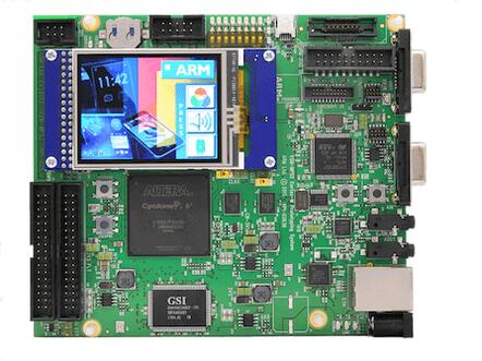
Arm Cortex-M3 (AN385)
24 MHz
4 MB flash + 4 MB RAM available
Part 2
접을 수 있는 영어 원문 전체
영어 원문 전체 펼치기
AFE1B631F7B59A405EA7A02708397C8D27C7C07527D95D9DB39E7A59FE68A75C
.. _mps2_an385_board:

ARM V2M MPS2
############

Overview
********

The mps2/an385 board configuration is used by Zephyr applications that run on
the V2M MPS2 board. It provides support for the ARM Cortex-M3 (AN385) CPU and
the following devices:

- Nested Vectored Interrupt Controller (NVIC)
- System Tick System Clock (SYSTICK)
- Cortex-M System Design Kit UART

.. image:: ../../../../../../../boards/arm/mps2/doc/img/mps2_an385.jpg
     :align: center
     :alt: ARM V2M MPS2

In addition to enabling actual hardware usage, this board configuration can
also use QEMU to emulate the AN385 platform running on the MPS2+.

More information about the board can be found at the `V2M MPS2 Website`_.

The Application Note AN385 can be found at `Application Note AN385`_.

.. note::
   This board configuration makes no claims about its suitability for use
   with actual MPS2 hardware systems using AN385, or any other hardware
   system. It has been tested on actual hardware, but its primary purpose is
   for use with QEMU and unit tests.

Hardware
********

ARM V2M MPS2 provides the following hardware components:

- ARM Cortex-M3 (AN385)
- ARM IoT Subsystem for Cortex-M
- Form factor: 140x120cm
- ZBTSRAM: 8MB single cycle SRAM, 16MB PSRAM
- Video: QSVGA touch screen panel, 4bit RGB VGA connector
- Audio: Audio Codec
- Debug:

  - ARM JTAG20 connector
  - ARM parallel trace connector (MICTOR38)
  - 20 pin Cortex debug connector
  - 10 pin Cortex debug connector
  - ILA connector for FPGA debug

- Expansion

  - GPIO
  - SPI

.. note::
   4 MB of flash memory (in ZBTSRAM 1, starting at address 0x00400000) and 4 MB of RAM
   (in ZBTSRAM 2 & 3, starting at address 0x20000000) are available.

Supported Features
==================

The mps2/an385 board configuration supports the following hardware features:

+-----------+------------+-------------------------------------+
| Interface | Controller | Driver/Component                    |
+===========+============+=====================================+
| NVIC      | on-chip    | nested vector interrupt controller  |
+-----------+------------+-------------------------------------+
| SYSTICK   | on-chip    | systick                             |
+-----------+------------+-------------------------------------+
| UART      | on-chip    | serial port-polling;                |
|           |            | serial port-interrupt               |
+-----------+------------+-------------------------------------+
| GPIO      | on-chip    | gpio                                |
+-----------+------------+-------------------------------------+
| WATCHDOG  | on-chip    | watchdog                            |
+-----------+------------+-------------------------------------+
| TIMER     | on-chip    | counter                             |
+-----------+------------+-------------------------------------+
| DUALTIMER | on-chip    | counter                             |
+-----------+------------+-------------------------------------+

Other hardware features are not currently supported by the port.
See the `V2M MPS2 Website`_ for a complete list of V2M MPS2 board hardware
features.

The default configuration can be found in
:zephyr_file:`boards/arm/mps2/mps2_an385_defconfig`

Interrupt Controller
====================

MPS2 is a Cortex-M3 based SoC and has 15 fixed exceptions and 45 IRQs.

A Cortex-M3/4-based board uses vectored exceptions. This means each exception
calls a handler directly from the vector table.

Handlers are provided for exceptions 1-6, 11-12, and 14-15. The table here
identifies the handlers used for each exception.

+------+------------+----------------+--------------------------+
| Exc# | Name       | Remarks        | Used by Zephyr Kernel    |
+======+============+================+==========================+
| 1    | Reset      |                | system initialization    |
+------+------------+----------------+--------------------------+
| 2    | NMI        |                | system fatal error       |
+------+------------+----------------+--------------------------+
| 3    | Hard fault |                | system fatal error       |
+------+------------+----------------+--------------------------+
| 4    | MemManage  | MPU fault      | system fatal error       |
+------+------------+----------------+--------------------------+
| 5    | Bus        |                | system fatal error       |
+------+------------+----------------+--------------------------+
| 6    | Usage      | undefined      | system fatal error       |
|      | fault      | instruction,   |                          |
|      |            | or switch      |                          |
|      |            | attempt to ARM |                          |
|      |            | mode           |                          |
+------+------------+----------------+--------------------------+
| 11   | SVC        |                | system calls, kernel     |
|      |            |                | run-time exceptions,     |
|      |            |                | and IRQ offloading       |
+------+------------+----------------+--------------------------+
| 12   | Debug      |                | system fatal error       |
|      | monitor    |                |                          |
+------+------------+----------------+--------------------------+
| 14   | PendSV     |                | context switch           |
+------+------------+----------------+--------------------------+
| 15   | SYSTICK    |                | system clock             |
+------+------------+----------------+--------------------------+

Pin Mapping
===========

The ARM V2M MPS2 Board has 4 GPIO controllers. These controllers are responsible
for pin muxing, input/output, pull-up, etc.

All GPIO controller pins are exposed via the following sequence of pin numbers:

- Pins 0 - 15 are for GPIO 0
- Pins 16 - 31 are for GPIO 1
- Pins 32 -  47 are for GPIO 2
- Pins 48 -  51 are for GPIO 3

Mapping from the ARM MPS2 Board pins to GPIO controllers:

.. rst-class:: rst-columns

   - D0 : EXT_0
   - D1 : EXT_4
   - D2 : EXT_2
   - D3 : EXT_3
   - D4 : EXT_1
   - D5 : EXT_6
   - D6 : EXT_7
   - D7 : EXT_8
   - D8 : EXT_9
   - D9 : EXT_10
   - D10 : EXT_12
   - D11 : EXT_13
   - D12 : EXT_14
   - D13 : EXT_11
   - D14 : EXT_15
   - D15 : EXT_5
   - D16 : EXT_16
   - D17 : EXT_17
   - D18 : EXT_18
   - D19 : EXT_19
   - D20 : EXT_20
   - D21 : EXT_21
   - D22 : EXT_22
   - D23 : EXT_23
   - D24 : EXT_24
   - D25 : EXT_25
   - D26 : EXT_26
   - D27 : EXT_30
   - D28 : EXT_28
   - D29 : EXT_29
   - D30 : EXT_27
   - D31 : EXT_32
   - D32 : EXT_33
   - D33 : EXT_34
   - D34 : EXT_35
   - D35 : EXT_36
   - D36 : EXT_38
   - D37 : EXT_39
   - D38 : EXT_40
   - D39 : EXT_44
   - D40 : EXT_41
   - D41 : EXT_31
   - D42 : EXT_37
   - D43 : EXT_42
   - D44 : EXT_43
   - D45 : EXT_45
   - D46 : EXT_46
   - D47 : EXT_47
   - D48 : EXT_48
   - D49 : EXT_49
   - D50 : EXT_50
   - D51 : EXT_51

Peripheral Mapping:

.. rst-class:: rst-columns

   - UART_3_RX : D0
   - UART_3_TX : D1
   - SPI_3_CS : D10
   - SPI_3_MOSI : D11
   - SPI_3_MISO : D12
   - SPI_3_SCLK : D13
   - I2C_3_SDA : D14
   - I2C_3_SCL : D15
   - UART_4_RX : D26
   - UART_4_TX : D30
   - SPI_4_CS : D36
   - SPI_4_MOSI : D37
   - SPI_4_MISO : D38
   - SPI_4_SCK : D39
   - I2C_4_SDA : D40
   - I2C_4_SCL : D41

For more details please refer to `MPS2 Technical Reference Manual (TRM)`_.

System Clock
============

The V2M MPS2 main clock is 24 MHz.

Serial Port
===========

The V2M MPS2 processor has five UARTs. Both the UARTs have only two wires for
RX/TX and no flow control (CTS/RTS) or FIFO. The Zephyr console output, by
default, is utilizing UART0.

Programming and Debugging
*************************

Flashing
========

V2M MPS2 provides:

- A USB connection to the host computer, which exposes a Mass Storage and an
  USB Serial Port.
- A Serial Flash device, which implements the USB flash disk file storage.
- A physical UART connection which is relayed over interface USB Serial port.

Flashing an application to V2M MPS2
-----------------------------------

Here is an example for the :ref:`hello_world` application.

.. zephyr-app-commands::
   :zephyr-app: samples/hello_world
   :board: mps2/an385
   :goals: build

Connect the V2M MPS2 to your host computer using the USB port and you should
see a USB connection which exposes a Mass Storage and a USB Serial Port.
Copy the generated zephyr.bin in the exposed drive.
Reset the board and you should be able to see on the corresponding Serial Port
the following message:

.. code-block:: console

   Hello World! arm


.. _V2M MPS2 Website:
   https://developer.mbed.org/platforms/ARM-MPS2/

.. _MPS2 Technical Reference Manual (TRM):
   http://infocenter.arm.com/help/topic/com.arm.doc.100112_0200_05_en/versatile_express_cortex_m_prototyping_systems_v2m_mps2_and_v2m_mps2plus_technical_reference_100112_0200_05_en.pdf

.. _Application Note AN385:
   http://infocenter.arm.com/help/topic/com.arm.doc.dai0385c/DAI0385C_cortex_m3_on_v2m_mps2.pdf
Part 3
한국어 전문 번역
개요
mps2/an385 보드 구성은 V2M MPS2에서 실행하는 Zephyr application용입니다. Arm Cortex-M3(AN385) CPU와 NVIC, SYSTICK, Cortex-M System Design Kit UART를 지원합니다.
실제 hardware뿐 아니라 QEMU로 MPS2+의 AN385 platform을 emulation할 수 있습니다. 자세한 내용은 V2M MPS2 website와 Application Note AN385를 참고합니다.
하드웨어
- Arm Cortex-M3(AN385)와 Cortex-M용 Arm IoT Subsystem
- form factor: 140 × 120 cm
- ZBTSRAM: 8 MB single-cycle SRAM, PSRAM: 16 MB
- video: QSVGA touch screen panel과 4-bit RGB VGA connector
- Audio Codec
- debug: Arm JTAG20, MICTOR38 parallel trace, 20-pin/10-pin Cortex debug, FPGA debug용 ILA connector
- expansion: GPIO, SPI
ZBTSRAM 1의 0x00400000부터 4 MB를 flash로, ZBTSRAM 2·3의 0x20000000부터 4 MB를 RAM으로 사용할 수 있습니다.
지원 기능
| Interface | Controller | Driver/Component |
|---|---|---|
| NVIC | on-chip | nested vector interrupt controller |
| SYSTICK | on-chip | systick |
| UART | on-chip | serial port-polling; serial port-interrupt |
| GPIO | on-chip | gpio |
| WATCHDOG | on-chip | watchdog |
| TIMER | on-chip | counter |
| DUALTIMER | on-chip | counter |
그 밖의 hardware는 현재 port에서 지원하지 않습니다. 전체 기능은 V2M MPS2 website를 참고하며 기본 구성은 boards/arm/mps2/mps2_an385_defconfig입니다.
Interrupt controller
MPS2는 Cortex-M3 기반 SoC로 15개의 fixed exception과 45개의 IRQ가 있습니다. Cortex-M3/4는 vectored exception을 사용하므로 각 exception이 vector table의 handler를 직접 호출합니다. Zephyr는 exception 1~6, 11~12, 14~15에 다음 handler를 제공합니다.
| Exc# | Name | Remarks | Zephyr kernel 용도 |
|---|---|---|---|
| 1 | Reset | system initialization | |
| 2 | NMI | system fatal error | |
| 3 | Hard fault | system fatal error | |
| 4 | MemManage | MPU fault | system fatal error |
| 5 | Bus | system fatal error | |
| 6 | Usage fault | undefined instruction 또는 ARM mode 전환 시도 | system fatal error |
| 11 | SVC | system calls, kernel run-time exceptions, IRQ offloading | |
| 12 | Debug monitor | system fatal error | |
| 14 | PendSV | context switch | |
| 15 | SYSTICK | system clock |
Pin mapping
4개 GPIO controller가 pin muxing, input/output, pull-up 등을 담당합니다. GPIO0은 pin 0~15, GPIO1은 16~31, GPIO2는 32~47, GPIO3은 48~51입니다.
| Signal / Board pin | GPIO / Digital pin |
|---|---|
| D0 | EXT_0 |
| D1 | EXT_4 |
| D2 | EXT_2 |
| D3 | EXT_3 |
| D4 | EXT_1 |
| D5 | EXT_6 |
| D6 | EXT_7 |
| D7 | EXT_8 |
| D8 | EXT_9 |
| D9 | EXT_10 |
| D10 | EXT_12 |
| D11 | EXT_13 |
| D12 | EXT_14 |
| D13 | EXT_11 |
| D14 | EXT_15 |
| D15 | EXT_5 |
| D16 | EXT_16 |
| D17 | EXT_17 |
| D18 | EXT_18 |
| D19 | EXT_19 |
| D20 | EXT_20 |
| D21 | EXT_21 |
| D22 | EXT_22 |
| D23 | EXT_23 |
| D24 | EXT_24 |
| D25 | EXT_25 |
| D26 | EXT_26 |
| D27 | EXT_30 |
| D28 | EXT_28 |
| D29 | EXT_29 |
| D30 | EXT_27 |
| D31 | EXT_32 |
| D32 | EXT_33 |
| D33 | EXT_34 |
| D34 | EXT_35 |
| D35 | EXT_36 |
| D36 | EXT_38 |
| D37 | EXT_39 |
| D38 | EXT_40 |
| D39 | EXT_44 |
| D40 | EXT_41 |
| D41 | EXT_31 |
| D42 | EXT_37 |
| D43 | EXT_42 |
| D44 | EXT_43 |
| D45 | EXT_45 |
| D46 | EXT_46 |
| D47 | EXT_47 |
| D48 | EXT_48 |
| D49 | EXT_49 |
| D50 | EXT_50 |
| D51 | EXT_51 |
Peripheral mapping
| Signal / Board pin | GPIO / Digital pin |
|---|---|
| UART_3_RX | D0 |
| UART_3_TX | D1 |
| SPI_3_CS | D10 |
| SPI_3_MOSI | D11 |
| SPI_3_MISO | D12 |
| SPI_3_SCLK | D13 |
| I2C_3_SDA | D14 |
| I2C_3_SCL | D15 |
| UART_4_RX | D26 |
| UART_4_TX | D30 |
| SPI_4_CS | D36 |
| SPI_4_MOSI | D37 |
| SPI_4_MISO | D38 |
| SPI_4_SCK | D39 |
| I2C_4_SDA | D40 |
| I2C_4_SCL | D41 |
자세한 내용은 MPS2 Technical Reference Manual(TRM)을 참고합니다.
Clock과 serial
V2M MPS2 main clock은 24 MHz입니다. processor에는 UART가 5개 있으며 RX/TX 두 선만 사용하고 CTS/RTS flow control과 FIFO는 없습니다. 기본 Zephyr console은 UART0입니다.
프로그래밍과 디버깅
USB 연결은 host에 Mass Storage와 USB Serial Port를 노출합니다. Serial Flash가 USB flash disk storage를 구현하며 physical UART는 USB Serial Port로 relay됩니다.
Application flashing
hello_world를 build합니다.
west build -b mps2/an385 samples/hello_worldUSB로 보드를 연결하고 노출된 drive에 생성된 zephyr.bin을 복사합니다. reset 후 해당 serial port에서 다음 출력을 확인합니다.
Hello World! arm참고 자료
Source
출처
영어 원문에는 문단, 문서 지시문, 표, 코드, 코드 심벌, 경로를 그대로 보존했습니다.