Part 1
요약·해설
Arduino Opta는 IEC-61131-3 PLC language와 Arduino programming을 지원하는 secure micro PLC입니다. Zephyr는 현재 M4만 지원하며 M7은 PLC task를 담당합니다.
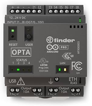
M7 PLC + Zephyr M4 coprocessor
analog input 8개, isolated relay 4개
USB DFU, RESET double-tap
Part 2
접을 수 있는 영어 원문 전체
영어 원문 전체 펼치기
D6074483E5B1BE58789FC8D77E715F5623FDA7F7040772B61D0BDB66E0129071
.. _arduino_opta_m4_board:

Arduino OPTA M4-Core
####################

Overview
********

The Arduino™ Opta® is a secure micro Programmable Logic Controller (PLC)
with Industrial Internet of Things (IoT) capabilities.

Developed in partnership with Finder®, this device supports both the Arduino
programming language and standard IEC-61131-3 PLC programming languages,
such as Ladder Diagram (LD), Sequential Function Chart (SFC),
Function Block Diagram (FBD), Structured Text (ST), and Instruction List (IL),
making it an ideal device for automation engineers.

For Zephyr RTOS, only the M4 is supported for now, making the M7 run the PLC
tasks while the M4 core under Zephyr acts as a coprocessor.

Additionally, the device features:

- Ethernet compliant with IEEE802.3-2002
- 16MB QSPI Flash
- 4 x green color status LEDs
- 1 x user push-button
- 1 x reset push-button accessible via pinhole
- 8 x analog inputs
- 4 x isolated relay outputs

.. image:: ../../../../../../../boards/arduino/opta/doc/img/arduino_opta.jpeg
     :align: center
     :alt: ARDUINO-OPTA

More information about the board can be found at the `ARDUINO-OPTA website`_.
More information about STM32H747XIH6 can be found here:

- `STM32H747XI on www.st.com`_
- `STM32H747xx reference manual`_
- `STM32H747xx datasheet`_

Supported Features
==================

The current Zephyr arduino_opta_m4 board configuration supports the following hardware features:

+-----------+------------+-------------------------------------+
| Interface | Controller | Driver/Component                    |
+===========+============+=====================================+
| NVIC      | on-chip    | nested vector interrupt controller  |
+-----------+------------+-------------------------------------+
| PINMUX    | on-chip    | pinmux                              |
+-----------+------------+-------------------------------------+
| GPIO      | on-chip    | gpio                                |
+-----------+------------+-------------------------------------+
| FLASH     | on-chip    | flash memory                        |
+-----------+------------+-------------------------------------+
| RNG       | on-chip    | True Random number generator        |
+-----------+------------+-------------------------------------+
| IPM       | on-chip    | virtual mailbox based on HSEM       |
+-----------+------------+-------------------------------------+

Other hardware features are not yet supported on Zephyr porting.

The default configuration per core can be found in the defconfig file:
:zephyr_file:`boards/arduino/opta/arduino_opta_stm32h747xx_m4_defconfig`

Pin Mapping
===========

ARDUINO OPTA M4 has access to the 9 GPIO controllers. These controllers are responsible for pin muxing,
input/output, pull-up, etc.

For more details please refer to `ARDUINO-OPTA website`_.

Default Zephyr Peripheral Mapping
---------------------------------

- Status LED1 : PI0
- Status LED2 : PI1
- Status LED3 : PI3
- Status LED4 : PH15
- User button : PE4

System Clock
============

The STM32H747I System Clock can be driven by an internal or external oscillator,
as well as by the main PLL clock. By default, the CPU2 (Cortex-M4) System clock
is driven at 240MHz. PLL clock is fed by a 25MHz high speed external clock.

Resources sharing
=================

The dual core nature of STM32H747 SoC requires sharing HW resources between the
two cores. This is done in 3 ways:

- **Compilation**: Clock configuration is only accessible to M7 core. M4 core only
  has access to bus clock activation and deactivation.
- **Static pre-compilation assignment**: Peripherals such as a UART are assigned in
  devicetree before compilation. The user must ensure peripherals are not assigned
  to both cores at the same time.
- **Run time protection**: Interrupt-controller and GPIO configurations could be
  accessed by both cores at run time. Accesses are protected by a hardware semaphore
  to avoid potential concurrent access issues.

Programming and Debugging
*************************

Applications for the ``arduino_opta`` use the regular Zephyr build commands.
See :ref:`build_an_application` for more information about application builds.

Flashing
========

Flashing operation will depend on the target to be flashed and the SoC
option bytes configuration. The OPTA has a DFU capable bootloader which
can be accessed by connecting the device to the USB, and then pressing
the RESET button shortly twice, the RESET-LED on the board will fade
indicating the board is in bootloader mode.

By default:

  - CPU2 (Cortex-M4) boot address is set to 0x08180000 (OB: BOOT_CM4_ADD0)

Zephyr flash configuration has been set to meet these default settings.

Flashing an application to ARDUINO OPTA M4
------------------------------------------

First, connect the device to your host computer using
the USB port to prepare it for flashing. Then build and flash your application.

Here is an example for the :zephyr:code-sample:`blinky` application on M4 core.

.. zephyr-app-commands::
   :zephyr-app: samples/basic/blinky
   :board: arduino_opta/stm32h747xx/m4
   :goals: build flash

Starting the application on the ARDUINO OPTA M4
-----------------------------------------------

Make sure the option bytes are set to prevent the M4 from auto-starting, and
that the M7 side starts the M4 at the correct Flash address.

This can be done by selecting in the Arduino IDE's "Tools" / "Flash Split"
menu the "1.5MB M7 + 0.5MB M4" option, and loading a sketch that contains
at least the following code:

 .. code-block:: cpp

    #include <RPC.h>

    void setup() {
        RPC.begin();
    }

    void loop() { }

Debugging
=========

Debugging is not yet supported by this board, since the debug port does
not have an easy access.

.. _ARDUINO-OPTA website:
   https://docs.arduino.cc/hardware/opta

.. _STM32H747XI on www.st.com:
   https://www.st.com/content/st_com/en/products/microcontrollers-microprocessors/stm32-32-bit-arm-cortex-mcus/stm32-high-performance-mcus/stm32h7-series/stm32h747-757/stm32h747xi.html

.. _STM32H747xx reference manual:
   https://www.st.com/resource/en/reference_manual/dm00176879.pdf

.. _STM32H747xx datasheet:
   https://www.st.com/resource/en/datasheet/stm32h747xi.pdf
Part 3
한국어 전문 번역
개요
Arduino Opta는 Finder와 공동 개발한 secure micro PLC이며 industrial IoT를 지원합니다. Arduino language와 IEC-61131-3의 LD, SFC, FBD, ST, IL을 지원합니다. Zephyr는 현재 M4만 지원하며 M7은 PLC task를 실행하고 M4 Zephyr는 coprocessor가 됩니다.
- IEEE 802.3-2002 Ethernet
- QSPI flash 16 MB
- green status LED 4개, user button, pinhole reset
- analog input 8개, isolated relay output 4개
지원 기능
| Interface | Controller | Driver/Component |
|---|---|---|
| NVIC | on-chip | nested vector interrupt controller |
| PINMUX | on-chip | pinmux |
| GPIO | on-chip | gpio |
| FLASH | on-chip | flash memory |
| RNG | on-chip | TRNG |
| IPM | on-chip | HSEM virtual mailbox |
다른 기능은 아직 지원하지 않습니다. M4 기본 설정은 boards/arduino/opta/arduino_opta_stm32h747xx_m4_defconfig입니다.
Pin mapping
GPIO controller 9개가 pin muxing, I/O와 pull-up을 담당합니다.
- Status LED1: PI0
- Status LED2: PI1
- Status LED3: PI3
- Status LED4: PH15
- User button: PE4
System clock
internal/external oscillator 또는 main PLL을 사용합니다. CPU2 Cortex-M4는 기본 240 MHz이며 PLL은 25 MHz external high-speed clock을 입력으로 받습니다.
Dual-core 자원 공유
STM32H747의 두 core는 다음 세 방식으로 hardware resource를 공유합니다.
- Compile: clock configuration은 M7만 접근하고 M4는 bus clock 활성·비활성만 제어합니다.
- Static pre-compilation assignment: UART 같은 peripheral은 devicetree에서 미리 core에 할당하며 두 core에 동시에 배정하면 안 됩니다.
- Run-time protection: 두 core가 접근할 수 있는 interrupt controller와 GPIO configuration은 hardware semaphore로 동시 접근을 막습니다.
프로그래밍과 디버깅
target과 SoC option byte에 따라 flash 방식이 달라집니다. USB 연결 후 RESET을 짧게 두 번 누르면 RESET LED가 fade하며 DFU bootloader mode로 진입합니다. CPU2 기본 boot address는 0x08180000(option byte BOOT_CM4_ADD0)이고 Zephyr flash 설정도 이에 맞습니다.
west build -b arduino_opta/stm32h747xx/m4 samples/basic/blinky
west flash
M4 application 시작
option byte로 M4 auto-start를 막고 M7이 올바른 flash address에서 M4를 시작해야 합니다. Arduino IDE의 Tools / Flash Split에서 1.5MB M7 + 0.5MB M4를 선택하고 최소 다음 sketch를 M7에 올립니다.
#include <RPC.h>

void setup() {
    RPC.begin();
}

void loop() { }
Debug
debug port에 쉽게 접근할 수 없어 현재 이 board에서는 debug를 지원하지 않습니다.
참고 자료
Source
출처
영어 원문에는 문단, 문서 지시문, 표, 코드, 코드 심벌, 경로를 그대로 보존했습니다.