Part 1
요약·해설
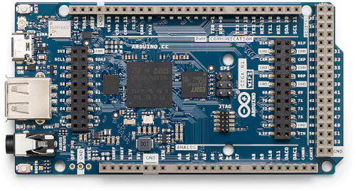
Arduino GIGA R1 WiFi는 STM32H747XI dual-core Cortex-M7 + M4, internal flash 2 MB, SRAM 1 MB, QSPI 16 MB와 SDRAM 8 MB를 갖습니다.
SoC
STM32H747XI Cortex-M7 + Cortex-M4
External
QSPI 16 MB, SDRAM 8 MB, Murata 1DX
Flash
Arduino USB-DFU 또는 MIPI-10 SWD
Part 2
접을 수 있는 영어 원문 전체
영어 원문 전체 펼치기
원문 SHA-256
A12A11040FC37CAC029531AA9B051A9762EDF0CE83C42E4B68D5B07E0B49D06E
.. _arduino_giga_r1_board:

Arduino GIGA R1 WiFi
####################

Overview
********

Arduino GIGA R1 WiFi is a development board by Arduino based on the
STM32H747XI, a dual core ARM Cortex-M7 + Cortex-M4 MCU, with 2MBytes of Flash
memory and 1MB SRAM.

The board features:

- RGB LED
- Reset and Boot buttons
- USB-C device
- USB Host
- 16MB external QSPI flash
- 8MB external SDRAM
- Murata Type 1DX Bluetooth + WiFi module (CYW4343W based)
- Audio jack
- ATECC608A secure element

.. image:: ../../../../../../../boards/arduino/giga_r1/doc/img/arduino_giga_r1.jpg
     :align: center
     :alt: Arduino GIGA R1 WiFi

More information about the board, including the datasheet, pinout and
schematics, can be found at the `Arduino GIGA website`_.

More information about STM32H747XIH6 can be found here:

- `STM32H747XI on www.st.com`_
- `STM32H747xx reference manual`_
- `STM32H747xx datasheet`_

Supported Features
==================

The current Zephyr ``arduino_giga_r1_m7`` board configuration supports the
following hardware features:

+-----------+------------+-------------------------------------+
| Interface | Controller | Driver/Component                    |
+===========+============+=====================================+
| NVIC      | on-chip    | nested vector interrupt controller  |
+-----------+------------+-------------------------------------+
| UART      | on-chip    | serial port-polling;                |
|           |            | serial port-interrupt               |
+-----------+------------+-------------------------------------+
| PINMUX    | on-chip    | pinmux                              |
+-----------+------------+-------------------------------------+
| GPIO      | on-chip    | gpio                                |
+-----------+------------+-------------------------------------+
| FLASH     | on-chip    | flash memory                        |
+-----------+------------+-------------------------------------+
| RNG       | on-chip    | True Random number generator        |
+-----------+------------+-------------------------------------+
| I2C       | on-chip    | i2c                                 |
+-----------+------------+-------------------------------------+
| SPI       | on-chip    | spi                                 |
+-----------+------------+-------------------------------------+
| IPM       | on-chip    | virtual mailbox based on HSEM       |
+-----------+------------+-------------------------------------+
| FMC       | on-chip    | memc (SDRAM)                        |
+-----------+------------+-------------------------------------+
| QSPI      | on-chip    | QSPI flash                          |
+-----------+------------+-------------------------------------+
| RADIO     | Murata 1DX | WiFi and Bluetooth module           |
+-----------+------------+-------------------------------------+

Other hardware features are not yet supported on Zephyr port.

Fetch Binary Blobs
******************

The board Bluetooth/WiFi module requires fetching some binary blob files, to do
that run the command:

.. code-block:: console

   west blobs fetch hal_infineon

.. note:: Only Bluetooth functionality is currently supported.

Resources sharing
=================

The dual core nature of STM32H747 SoC requires sharing HW resources between the
two cores. This is done in 3 ways:

- **Compilation**: Clock configuration is only accessible to M7 core. M4 core only
  has access to bus clock activation and deactivation.
- **Static pre-compilation assignment**: Peripherals such as a UART are assigned in
  devicetree before compilation. The user must ensure peripherals are not assigned
  to both cores at the same time.
- **Run time protection**: Interrupt-controller and GPIO configurations could be
  accessed by both cores at run time. Accesses are protected by a hardware semaphore
  to avoid potential concurrent access issues.

Programming and Debugging
*************************

Applications for the ``arduino_giga_r1`` board should be built per core target,
using either ``arduino_giga_r1/stm32h747xx/m7`` or ``arduino_giga_r1/stm32h747xx/m4`` as the target.

See :ref:`build_an_application` for more information about application builds.

Flashing
========

This board can be flashed either using dfu-util, or with an external debugging
probe, such as a J-Link or Black Magic Probe, connected to the on board MIPI-10
SWD port marked as "JTAG".

.. note::

   The board ships with a custom Arduino bootloader programmed in the first
   flash page that can be triggered by double clicking the ``RST`` button. This
   bootloader is USB-DFU compatible and supports programming both the internal
   and external flash and is the one used by ``west flash`` by default. The
   internal STM32 ROM bootloader can also be used by pressing ``RST`` while
   holding the ``BOOT0`` button, this also supports USB-DFU but can only
   program the internal flash and can overwrite the Arduino bootloader. More
   details can be found in the "Boot0" section of the `Arduino GIGA Cheat
   Sheet`_.

First, connect the Arduino GIGA R1 board to your host computer using the USB
port to prepare it for flashing. Double click the ``RST`` button to put the
board into the Arduino Bootloader mode. Then build and flash your application.

Here is an example for the :ref:`hello_world` application.

.. zephyr-app-commands::
   :zephyr-app: samples/hello_world
   :board: arduino_giga_r1/stm32h747xx/m7
   :goals: build flash

Run a serial host program to connect with your board:

.. code-block:: console

   $ minicom -D /dev/ttyACM0

You should see the following message on the console:

.. code-block:: console

   Hello World! arduino_giga_r1

Similarly, you can build and flash samples on the M4 target.

Here is an example for the :zephyr:code-sample:`blinky` application on M4 core.

.. zephyr-app-commands::
   :zephyr-app: samples/basic/blinky
   :board: arduino_giga_r1/stm32h747xx/m4
   :goals: build flash

Debugging
=========

Debugging is supported by using ``west debug`` with an external probe such as a
J-Link or Black Magic Probe, connected to the on board MIPI-10 SWD port marked
as "JTAG". For example::

  west debug -r jlink

.. _Arduino GIGA website:
   https://docs.arduino.cc/hardware/giga-r1-wifi

.. _Arduino GIGA Cheat Sheet:
   https://docs.arduino.cc/tutorials/giga-r1-wifi/cheat-sheet

.. _STM32H747XI on www.st.com:
   https://www.st.com/content/st_com/en/products/microcontrollers-microprocessors/stm32-32-bit-arm-cortex-mcus/stm32-high-performance-mcus/stm32h7-series/stm32h747-757/stm32h747xi.html

.. _STM32H747xx reference manual:
   https://www.st.com/resource/en/reference_manual/dm00176879.pdf

.. _STM32H747xx datasheet:
   https://www.st.com/resource/en/datasheet/stm32h747xi.pdf

.. _dfu-util:
   http://dfu-util.sourceforge.net/build.html
Part 3
한국어 전문 번역
개요
Arduino GIGA R1 WiFi는 dual-core Cortex-M7 + Cortex-M4 STM32H747XI, flash 2 MB와 SRAM 1 MB 기반 development board입니다.
- RGB LED, Reset·Boot button
- USB-C device와 USB host
- external QSPI flash 16 MB, SDRAM 8 MB
- CYW4343W 기반 Murata Type 1DX Bluetooth + Wi-Fi
- audio jack와 ATECC608A secure element
지원 기능
| Interface | Controller | Driver/Component |
|---|---|---|
| NVIC | on-chip | nested vector interrupt controller |
| UART | on-chip | serial polling·interrupt |
| PINMUX | on-chip | pinmux |
| GPIO | on-chip | gpio |
| FLASH | on-chip | flash memory |
| RNG | on-chip | TRNG |
| I2C | on-chip | i2c |
| SPI | on-chip | spi |
| IPM | on-chip | HSEM virtual mailbox |
| FMC | on-chip | SDRAM memc |
| QSPI | on-chip | QSPI flash |
| RADIO | Murata 1DX | Wi-Fi and Bluetooth module |
다른 기능은 아직 지원하지 않습니다.
Binary blob
Bluetooth/Wi-Fi module firmware blob을 받습니다. 현재는 Bluetooth만 지원합니다.
west blobs fetch hal_infineonDual-core 자원 공유
- Compile: clock configuration은 M7만 접근하고 M4는 bus clock 활성/비활성만 접근합니다.
- Static assignment: UART 같은 peripheral은 compile 전 devicetree에서 core에 할당합니다. 두 core에 동시에 배정하면 안 됩니다.
- Run-time protection: 두 core가 접근할 수 있는 interrupt controller와 GPIO는 hardware semaphore로 동시 접근을 막습니다.
프로그래밍과 디버깅
M7 target은 arduino_giga_r1/stm32h747xx/m7, M4 target은 arduino_giga_r1/stm32h747xx/m4입니다. dfu-util 또는 JTAG 표시 MIPI-10 SWD의 J-Link/Black Magic Probe를 사용할 수 있습니다.
M7 hello_world
USB로 연결하고 RST를 두 번 눌러 Arduino bootloader mode에 진입합니다.
west build -b arduino_giga_r1/stm32h747xx/m7 samples/hello_world
west flash
$ minicom -D /dev/ttyACM0
Hello World! arduino_giga_r1
M4 blinky
west build -b arduino_giga_r1/stm32h747xx/m4 samples/basic/blinky
west flash
Debug
external probe를 MIPI-10 SWD에 연결합니다.
west debug -r jlink참고 자료
Source
출처
영어 원문에는 문단, 문서 지시문, 표, 코드, 코드 심벌, 경로를 그대로 보존했습니다.