Part 1
요약·해설
ADP-XC7K AE350은 1~4개의 32/64-bit 60 MHz RISC-V core, DSP, RAM 1 GB, SPI flash와 Ethernet을 FPGA board에 구성합니다.
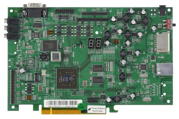
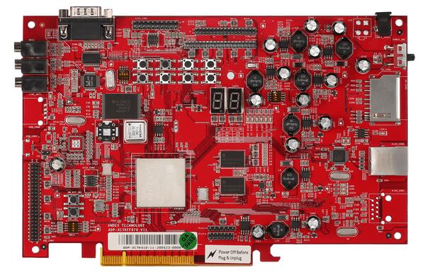
1~4 core, 32/64-bit 60 MHz AndeStar v5
SDRAM 1 GB, SPI flash 2 MB
AICE + ICEman, GDB port 1111
Part 2
접을 수 있는 영어 원문 전체
영어 원문 전체 펼치기
B3C5BE1DA2F0ACFBC791CBFFC2DC49DD151BF1C9187DF43C6EB494A25A0C012A
.. _adp_xc7k_ae350:

Andes ADP-XC7K AE350
####################

Overview
********

ADP-XC7K AE350 board is for AndeShape AE350 platform on ADP-XC7K series
FPGA-based development boards.

ADP-XC7K series are FPGA-based development and prototyping boards for evaluation of
variety of AndesCore processors and AndeShape SoC platform IPs.
AE350 is a RISC-V platform which can integrate AndesCore CPUs with a collection
of fundamental peripheral IPs.

1st figure shows the green PCB is ADP-XC7K160 and 2nd figure shows the red PCB is ADP-XC7K410.

.. image:: ../../../../../../../boards/andestech/adp_xc7k_ae350/doc/img/adp_xc7k160.jpg
     :align: center
     :alt: ADP-XC7K160

.. image:: ../../../../../../../boards/andestech/adp_xc7k_ae350/doc/img/adp_xc7k410.jpg
     :align: center
     :alt: ADP-XC7K410

More information can be found on `ADP-XC7K160/410`_ and `AndeShape AE350`_ websites.

Hardware
********

The ADP-XC7K AE350 platform integrates 1 ~ 4 cores 32/64-bit 60MHz RISC-V CPUs, DSP,
1GB RAM, Cache, SPI flash memory, ethernet controller and other peripherals.

The ADP-XC7K AE350 platform provides following hardware components:

- 1 ~ 4 cores 32/64-bit 60MHz AndeStar v5 RISC-V CPUs
- 1GB on-board SDRAM
- 2MB SPI flash memory (1MB can be used for XIP)
- UART
- I2C
- SPI
- GPIO
- PWM
- DMA
- 10/100 Ethernet RJ45 port
- LCD module connector
- 16KB I2C EEPROM
- SD memory card slot
- MIC-in, Line-in, and Line-out with AC97 audio codec

Supported Features
==================

The ``adp_xc7k/ae350`` board configuration supports the following hardware features:

+----------------+------------+----------------------+
| Interface      | Controller | Driver/Component     |
+================+============+======================+
| PLIC           | on-chip    | interrupt_controller |
+----------------+------------+----------------------+
| RISC-V Machine | on-chip    | timer                |
| Timer          |            |                      |
+----------------+------------+----------------------+
| GPIO           | on-chip    | gpio                 |
+----------------+------------+----------------------+
| UART           | on-chip    | serial               |
+----------------+------------+----------------------+
| COUNTER        | on-chip    | counter              |
+----------------+------------+----------------------+
| SPI            | on-chip    | spi                  |
+----------------+------------+----------------------+
| I2C            | on-chip    | i2c                  |
+----------------+------------+----------------------+
| EEPROM         | on-chip    | eeprom               |
+----------------+------------+----------------------+
| FLASH          | on-chip    | flash                |
+----------------+------------+----------------------+
| HWINFO         | on-chip    | syscon               |
+----------------+------------+----------------------+
| MAILBOX        | on-chip    | mbox                 |
+----------------+------------+----------------------+
| DMA            | on-chip    | dma                  |
+----------------+------------+----------------------+
| WATCHDOG       | on-chip    | wdt                  |
+----------------+------------+----------------------+

Other hardware features are not supported yet.

Connections and IOs
===================

The ADP-XC7K AE350 platform has 1 GPIO controller. It providing 32 bits of IO.
It is responsible for pin input/output, pull-up, etc.

Mapping from GPIO controller to the ADP-XC7K board pins:

+--------------------+--------------------+
| GPIO controller    | Usage / Board pins |
+====================+====================+
| **Push Buttons**   |                    |
+--------------------+--------------------+
| GPIO.0             | SW1                |
+--------------------+--------------------+
| GPIO.1             | SW2                |
+--------------------+--------------------+
| GPIO.2             | SW3                |
+--------------------+--------------------+
| GPIO.3             | SW4                |
+--------------------+--------------------+
| GPIO.4             | SW5                |
+--------------------+--------------------+
| GPIO.5             | SW6                |
+--------------------+--------------------+
| GPIO.6             | SW7                |
+--------------------+--------------------+
| **7-Segment LED1** |                    |
+--------------------+--------------------+
| GPIO.16            | 7SEG1.A            |
+--------------------+--------------------+
| GPIO.17            | 7SEG1.B            |
+--------------------+--------------------+
| GPIO.18            | 7SEG1.C            |
+--------------------+--------------------+
| GPIO.19            | 7SEG1.D            |
+--------------------+--------------------+
| GPIO.20            | 7SEG1.E            |
+--------------------+--------------------+
| GPIO.21            | 7SEG1.F            |
+--------------------+--------------------+
| GPIO.22            | 7SEG1.G            |
+--------------------+--------------------+
| GPIO.23            | 7SEG1.DP           |
+--------------------+--------------------+
| **7-Segment LED2** |                    |
+--------------------+--------------------+
| GPIO.24            | 7SEG2.A            |
+--------------------+--------------------+
| GPIO.25            | 7SEG2.B            |
+--------------------+--------------------+
| GPIO.26            | 7SEG2.C            |
+--------------------+--------------------+
| GPIO.27            | 7SEG2.D            |
+--------------------+--------------------+
| GPIO.28            | 7SEG2.E            |
+--------------------+--------------------+
| GPIO.29            | 7SEG2.F            |
+--------------------+--------------------+
| GPIO.30            | 7SEG2.G            |
+--------------------+--------------------+
| GPIO.31            | 7SEG2.DP           |
+--------------------+--------------------+
| **GPIO pins**      |                    |
+--------------------+--------------------+
| GPIO.7             | IDE_CON1.4         |
+--------------------+--------------------+
| GPIO.8             | IDE_CON1.6         |
+--------------------+--------------------+
| GPIO.9             | IDE_CON1.8         |
+--------------------+--------------------+
| GPIO.10            | IDE_CON1.10        |
+--------------------+--------------------+
| GPIO.11            | IDE_CON1.11        |
+--------------------+--------------------+
| GPIO.12            | IDE_CON1.12        |
+--------------------+--------------------+
| GPIO.13            | IDE_CON1.13        |
+--------------------+--------------------+
| GPIO.14            | IDE_CON1.14        |
+--------------------+--------------------+
| GPIO.15            | IDE_CON1.15        |
+--------------------+--------------------+

Other peripheral mapping are listed below:

+-------------+---------------------------------+
| Peripherals | Usage / Board pins              |
+=============+=================================+
| SPI_1       | internal connected to SPI Flash |
+-------------+---------------------------------+
| SPI_2_CS    | IDE_CON1.37                     |
+-------------+---------------------------------+
| SPI_2_MOSI  | IDE_CON1.36                     |
+-------------+---------------------------------+
| SPI_2_MISO  | IDE_CON1.38                     |
+-------------+---------------------------------+
| SPI_2_SCLK  | IDE_CON1.35                     |
+-------------+---------------------------------+
| I2C_SDA     | J27.1                           |
+-------------+---------------------------------+
| I2C_SCL     | J27.2                           |
+-------------+---------------------------------+

System Clock
------------

The ADP-XC7K AE350 platform has 60MHz core clock.

Serial Port
-----------

The ADP-XC7K AE350 platform has 2 UARTs.
The Zephyr console output is by default assigned to UART2 and the default
settings are 115200 8N1.

Programming and debugging
*************************

For debugging zephyr applications or burning them into a flash, you will need to
connect Andes ICE from host computer to ADP-XC7K board and execute the
Andes ICE management software, ICEman, on this host computer.

Connecting Andes ICE (AICE)
===========================

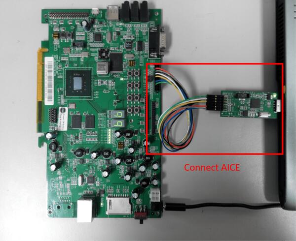
AICE is used for flashing and debugging the board. Please connect AICE to both
ADP-XC7K board and the host computer as shown in the figure.

.. image:: ../../../../../../../boards/andestech/adp_xc7k_ae350/doc/img/connect_aice.jpg
     :align: center
     :alt: Connect AICE

More information can be found on `AICE-MINI+`_, `AICE-MICRO`_ website

Building
========

You can build applications in the usual way. Here is an example for
the :ref:`hello_world` application.

.. zephyr-app-commands::
   :zephyr-app: samples/hello_world
   :board: adp_xc7k/ae350
   :goals: build

Flashing
========

Before flashing, you have to download ICEman (``ice.zip``) from the
`Andes Development Kit`_.
If you want to use XIP mode (``CONFIG_XIP=y``), you also need to download
the flash burner (``flash.zip``).

At first, you should run ICEman when flashing and debugging program.

.. code-block:: console

   # Enable execute file permission of ICEman
   chmod a+x ./ICEman

   # Running the ICEman server
   sudo ./ICEman -Z v5

.. note::

   To run ICEman commands as a normal user, you will need to install the
   :file:`70-ndsusb-v1.rules` udev rules file (usually by placing it in
   :file:`/etc/udev/rules.d`, then unplugging and plugging the
   AICE adapter in again via USB.).

If ``CONFIG_XIP=n``, you can load the program (``zephyr.elf``) into RAM directly
and execute it.

.. code-block:: console

   # Check the ICEman server is running
   # Load the program into RAM and execute it
   riscv64-zephyr-elf-gdb build/zephyr/zephyr.elf
   (gdb) target remote :1111
   (gdb) monitor reset halt
   (gdb) load
   (gdb) quit

If ``CONFIG_XIP=y``, you need to burn the program (``zephyr.bin``) into flash memory
and execute it.

.. code-block:: console

   # Check the ICEman server is running
   # Burn the program into flash and execute it
   <FLASH>/bin/target_burn_frontend \
       -P 4444 --unlock --verify --image=build/zephyr/zephyr.bin \
       --algorithm-bin=<FLASH>/target_bin/target_SPI_v5_[32|64].bin

   # Note:
   #   1. Assume the flash burner is downloaded to <FLASH> directory
   #   2. For algorithm-bin file, use target_SPI_v5_32.bin in RV32 platform and
   #      use target_SPI_v5_64.bin in RV64 platform

Open a serial terminal with the following settings:

- Speed: 115200
- Data: 8 bits
- Parity: None
- Stop bits: 1

you should see the following message in the terminal:

.. code-block:: console

   ***** Booting Zephyr OS v2.4.0 *****
   Hello World! adp_xc7k

Debugging
=========

.. code-block:: console

   # Check the ICEman server is running
   # Load and debug program
   ./riscv64-zephyr-elf-gdb build/zephyr/zephyr.elf
   (gdb) target remote :1111
   (gdb) monitor reset halt
   (gdb) load

If ``CONFIG_XIP=y``, please follow the flashing section to burn the program into
flash memory first.
Then, you can use GDB to debug program by above commands but do NOT execute ``load``
command since the program has been placed in the flash memory.

References
**********

.. target-notes::

.. _ADP-XC7K160/410: http://www.andestech.com/en/products-solutions/andeshape-platforms/adp-xc7k160-410/

.. _AndeShape AE350: http://www.andestech.com/en/products-solutions/andeshape-platforms/ae350-axi-based-platform-pre-integrated-with-n25f-nx25f-a25-ax25/

.. _AICE-MINI+: http://www.andestech.com/en/products-solutions/andeshape-platforms/aice-mini-plus/

.. _AICE-MICRO: http://www.andestech.com/en/products-solutions/andeshape-platforms/aice-micro/

.. _Andes Development Kit: https://github.com/andestech/Andes-Development-Kit/releases
Part 3
한국어 전문 번역
개요
ADP-XC7K AE350 board는 ADP-XC7K series FPGA development board 위의 AndeShape AE350 platform입니다. ADP-XC7K는 여러 AndesCore processor와 AndeShape SoC IP를 평가·prototype하며, AE350은 AndesCore CPU와 기본 peripheral IP를 통합하는 RISC-V platform입니다.
첫 이미지는 green PCB ADP-XC7K160, 두 번째는 red PCB ADP-XC7K410입니다.
하드웨어
1~4 core 32/64-bit 60 MHz RISC-V CPU, DSP, RAM 1 GB, cache, SPI flash, Ethernet controller와 peripheral을 통합합니다.
- AndeStar v5 RISC-V CPU 1~4개
- on-board SDRAM 1 GB
- SPI flash 2 MB, 그중 1 MB는 XIP 가능
- UART, I2C, SPI, GPIO, PWM, DMA
- 10/100 Ethernet RJ45와 LCD module connector
- I2C EEPROM 16 KB, SD card slot
- AC97 codec의 MIC-in, line-in, line-out
지원 기능
| Interface | Controller | Driver/Component |
|---|---|---|
| PLIC | on-chip | interrupt_controller |
| RISC-V Machine Timer | on-chip | timer |
| GPIO | on-chip | gpio |
| UART | on-chip | serial |
| COUNTER | on-chip | counter |
| SPI | on-chip | spi |
| I2C | on-chip | i2c |
| EEPROM | on-chip | eeprom |
| FLASH | on-chip | flash |
| HWINFO | on-chip | syscon |
| MAILBOX | on-chip | mbox |
| DMA | on-chip | dma |
| WATCHDOG | on-chip | wdt |
다른 기능은 아직 지원하지 않습니다.
연결과 I/O
GPIO controller 하나가 32-bit I/O의 input/output과 pull-up을 담당합니다.
| GPIO | Usage / Board pin |
|---|---|
| GPIO.0 | SW1 |
| GPIO.1 | SW2 |
| GPIO.2 | SW3 |
| GPIO.3 | SW4 |
| GPIO.4 | SW5 |
| GPIO.5 | SW6 |
| GPIO.6 | SW7 |
| GPIO.16 | 7SEG1.A |
| GPIO.17 | 7SEG1.B |
| GPIO.18 | 7SEG1.C |
| GPIO.19 | 7SEG1.D |
| GPIO.20 | 7SEG1.E |
| GPIO.21 | 7SEG1.F |
| GPIO.22 | 7SEG1.G |
| GPIO.23 | 7SEG1.DP |
| GPIO.24 | 7SEG2.A |
| GPIO.25 | 7SEG2.B |
| GPIO.26 | 7SEG2.C |
| GPIO.27 | 7SEG2.D |
| GPIO.28 | 7SEG2.E |
| GPIO.29 | 7SEG2.F |
| GPIO.30 | 7SEG2.G |
| GPIO.31 | 7SEG2.DP |
| GPIO.7 | IDE_CON1.4 |
| GPIO.8 | IDE_CON1.6 |
| GPIO.9 | IDE_CON1.8 |
| GPIO.10 | IDE_CON1.10 |
| GPIO.11 | IDE_CON1.11 |
| GPIO.12 | IDE_CON1.12 |
| GPIO.13 | IDE_CON1.13 |
| GPIO.14 | IDE_CON1.14 |
| GPIO.15 | IDE_CON1.15 |
| Peripheral | Usage / Board pin |
|---|---|
| SPI_1 | internal SPI flash |
| SPI_2_CS | IDE_CON1.37 |
| SPI_2_MOSI | IDE_CON1.36 |
| SPI_2_MISO | IDE_CON1.38 |
| SPI_2_SCLK | IDE_CON1.35 |
| I2C_SDA | J27.1 |
| I2C_SCL | J27.2 |
Clock·console
core clock은 60 MHz입니다. UART 2개 중 Zephyr console은 기본 UART2, 115200 8N1입니다.
프로그래밍과 디버깅
Zephyr application debug와 flash에는 host와 ADP-XC7K를 연결하는 Andes ICE(AICE), 그리고 host의 ICEman server가 필요합니다.
Build
west build -b adp_xc7k/ae350 samples/hello_worldICEman
Andes Development Kit에서 ice.zip을 받습니다. XIP면 flash.zip도 필요합니다.
# Enable execute permission
chmod a+x ./ICEman
# Run ICEman server
sudo ./ICEman -Z v5RAM 실행, CONFIG_XIP=n
riscv64-zephyr-elf-gdb build/zephyr/zephyr.elf
(gdb) target remote :1111
(gdb) monitor reset halt
(gdb) load
(gdb) quit
Flash 실행, CONFIG_XIP=y
<FLASH>/bin/target_burn_frontend \
    -P 4444 --unlock --verify --image=build/zephyr/zephyr.bin \
--algorithm-bin=<FLASH>/target_bin/target_SPI_v5_[32|64].bin<FLASH>는 flash burner directory입니다. RV32는 target_SPI_v5_32.bin, RV64는 target_SPI_v5_64.bin을 사용합니다.
serial terminal은 115200 baud, 8 data bit, parity none, stop bit 1입니다.
***** Booting Zephyr OS v2.4.0 *****
Hello World! adp_xc7k
Debug
./riscv64-zephyr-elf-gdb build/zephyr/zephyr.elf
(gdb) target remote :1111
(gdb) monitor reset halt
(gdb) loadCONFIG_XIP=y이면 먼저 flash에 기록한 뒤 같은 GDB 명령을 쓰되 이미 flash에 program이 있으므로 load를 실행하지 않습니다.
참고 자료
Source
출처
영어 원문에는 문단, 문서 지시문, 표, 코드, 코드 심벌, 경로를 그대로 보존했습니다.