Part 1
요약·해설
MAX32680EVKIT는 industrial·medical sensor용 MAX32680 SoC를 평가합니다. SIMO regulator, Bluetooth 5.2 LE와 두 precision sigma-delta ADC를 한 board에서 다룹니다.
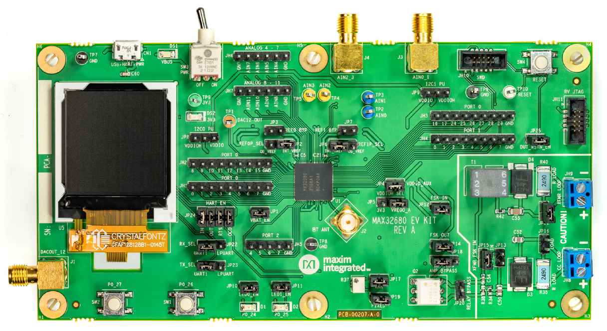
Bluetooth 5.2 LE, RISC-V radio coprocessor
16~24-bit sigma-delta ADC 2개, 12 channels
HART analog circuit와 current/transformer loop
Part 2
접을 수 있는 영어 원문 전체
영어 원문 전체 펼치기
33CB3D030152FBF5492250DA52BBF17EC509880ED59260FAC9DBF1D1BB255F2A
.. _max32680_evkit:
MAX32680EVKIT
#############
Overview
********
The MAX32680 evaluation kit (EV kit) provides a platform
for evaluation capabilities of the MAX32680 microcontroller,
which is an advanced system-on-chip (SoC)
designed for industrial and medical sensors. Power regulation
and management is provided by a single-inductor
multiple-output (SIMO) buck regulator system and contains
the latest generation Bluetooth® 5.2 Low Energy
(LE) radio.
The Zephyr port is running on the MAX32680 MCU.
.. image:: ../../../../../../../boards/adi/max32680evkit/doc/img/max32680evkit_img1.jpg
:align: center
:alt: MAX32680 EVKIT
Hardware
********
- MAX32680 MCU:
- Ultra-Low-Power Wireless Microcontroller
- Internal 100MHz Oscillator
- 512KB Flash and 128KB SRAM, Optional ECC on One 32KB SRAM Bank
- Bluetooth 5.2 LE Radio
- Dedicated, Ultra-Low-Power, 32-Bit RISC-VCoprocessor to Offload
Timing-Critical Bluetooth Processing
- Fully Open-Source Bluetooth 5.2 Stack Available
- Supports AoA, AoD, LE Audio, and Mesh
- High-Throughput (2Mbps) Mode•Long-Range (125kbps and 500kbps) Modes
- Rx Sensitivity: -97.5dBm; Tx Power: +4.5dBm
- Single-Ended Antenna Connection (50Ω)
- Smart Integration Reduces BOM, Cost, and PCB Size
- Two 16-Bit to 24-Bit Sigma-Delta ADCs
- 12 Channels, Assignable to Either ADC
- Flexible Resolution and Sample Rates
- 24-Bits at 0.4ksps, 16-Bits at 4ksps
- Four External Input, 10-Bit Sigma-Delta ADC 7.8ksps
- 12-Bit DAC
- On-Die Temperature Sensor
- Digital Peripherals: Two SPI, Two I2C, up to FourUART, and up to 36 GPIOs
- Timers: Six 32-Bit Timers, Two Watchdog Timers,Two Pulse Trains, 1-Wire® Master
- Power Management Maximizes Battery Life
- 2.0V to 3.6V Supply Voltage Range
- Integrated SIMO Power Regulator
- Dynamic Voltage Scaling (DVS)
- 23.8μA/MHz ACTIVE Mode Current at 3.0VCoremark®
- 4.4μA at 3.0V Retention Current for 32KB SRAM
- Selectable SRAM Retention in Low-Power Modes
- Robust Security and Reliability
- TRNG
- Secure Nonvolatile Key Storage and AES-128/192/256
- Secure Boot to Protect IP/Firmware
- Wide, -40°C to +85°C Operating Temperature
- External devices connected to the MAX32680 EVKIT:
- SMA Connector for Attaching an External Bluetooth Antenna
- 128 x 128 (1.45in) Color TFT Display with SPI Interface
- Two Selectable On-Board, High-Precision Voltage References
- USB 2.0 Micro B to Serial UARTs
- UART1 and LPUART0 Interface is Selectable Through On-Board Jumpers
- All GPIOs Signals Accessed Through 0.1in Headers
- Access to Four Analog Inputs Through SMA Connectors Configured as Differential
- Access to Eight Analog Inputs Through 0.1in Headers Configured as Single-End
- Optional Discrete Filter for the Twelve Analog Inputs
- DAC Accessed Through SMA Connector or Test Point
- 10-Pin SWD Connector
- 10-Pin RV JTAG Connector
- Board Power Provided by USB Port
- On-Board 3.3V LDO Regulator to Power MAX32680 Internal SIMO
- Test Loops Provided to Supply Optional VCORE Power Externally
- Individual Power Measurement on All IC Rails Through Jumpers
- Two General Purpose LEDs and Two General Purpose Pushbutton Switches
Supported Features
==================
Below interfaces are supported by Zephyr on MAX32680EVKIT.
+-----------+------------+-------------------------------------+
| Interface | Controller | Driver/Component |
+===========+============+=====================================+
| NVIC | on-chip | nested vector interrupt controller |
+-----------+------------+-------------------------------------+
| SYSTICK | on-chip | systick |
+-----------+------------+-------------------------------------+
| CLOCK | on-chip | clock and reset control |
+-----------+------------+-------------------------------------+
| GPIO | on-chip | gpio |
+-----------+------------+-------------------------------------+
| UART | on-chip | serial |
+-----------+------------+-------------------------------------+
Connections and IOs
===================
+-----------+---------------+---------------+--------------------------------------------------------------------------------------------------+
| Name | Name | Settings | Description |
+===========+===============+===============+==================================================================================================+
| JP1 | VREGI | | |
| | | +-----------+ | +-------------------------------------------------------------------------------+ |
| | | | Open | | | Disconnects 3.3V power from the MAX32680 SIMO. | |
| | | +-----------+ | +-------------------------------------------------------------------------------+ |
| | | | Closed | | | Connects 3.3V power to the MAX32680 SIMO. | |
| | | +-----------+ | +-------------------------------------------------------------------------------+ |
| | | | |
+-----------+---------------+---------------+--------------------------------------------------------------------------------------------------+
| JP2 | REF0P | +-----------+ | +-------------------------------------------------------------------------------+ |
| | | | 2-1 | | | Connects the external high-precision voltage refernce to REF0P. | |
| | | +-----------+ | +-------------------------------------------------------------------------------+ |
| | | | 2-3 | | | Connects the internal voltage refernce to REF0P. | |
| | | +-----------+ | +-------------------------------------------------------------------------------+ |
| | | | |
+-----------+---------------+---------------+--------------------------------------------------------------------------------------------------+
| JP3 | REF0N | +-----------+ | +-------------------------------------------------------------------------------+ |
| | | | Open | | | Disconnects REF0N from ground. | |
| | | +-----------+ | +-------------------------------------------------------------------------------+ |
| | | | Closed | | | Connects REF0N to ground. | |
| | | +-----------+ | +-------------------------------------------------------------------------------+ |
| | | | |
+-----------+---------------+---------------+--------------------------------------------------------------------------------------------------+
| JP4 | VDDIO_AUX | +-----------+ | +-------------------------------------------------------------------------------+ |
| | | | Open | | | Disconnects VDDIO_AUX from pull-ups and reference voltages. | |
| | | +-----------+ | +-------------------------------------------------------------------------------+ |
| | | | Closed | | | Connects VDDIO_AUX to pull-ups and reference voltages. | |
| | | +-----------+ | +-------------------------------------------------------------------------------+ |
| | | | |
+-----------+---------------+---------------+--------------------------------------------------------------------------------------------------+
| JP5 | VDDIOH | +-----------+ | +-------------------------------------------------------------------------------+ |
| | | | Open | | | Connects VREGO_A to VDDIOH. | |
| | | +-----------+ | +-------------------------------------------------------------------------------+ |
| | | | Closed | | | Connects the 3.3V from the estrenal LDO to VDDIOH. | |
| | | +-----------+ | +-------------------------------------------------------------------------------+ |
| | | | |
+-----------+---------------+---------------+--------------------------------------------------------------------------------------------------+
| JP6 | REF1P | +-----------+ | +-------------------------------------------------------------------------------+ |
| | | | 2-1 | | | Connects the external high-precision voltage refernce to REF1P. | |
| | | +-----------+ | +-------------------------------------------------------------------------------+ |
| | | | 2-3 | | | Connects the internal voltage refernce to REF1P. | |
| | | +-----------+ | +-------------------------------------------------------------------------------+ |
| | | | |
+-----------+---------------+---------------+--------------------------------------------------------------------------------------------------+
| JP7 | REF1N | +-----------+ | +-------------------------------------------------------------------------------+ |
| | | | Open | | | Disconnects REF1N from ground. | |
| | | +-----------+ | +-------------------------------------------------------------------------------+ |
| | | | Closed | | | Connects REF1N to ground. | |
| | | +-----------+ | +-------------------------------------------------------------------------------+ |
| | | | |
+-----------+---------------+---------------+--------------------------------------------------------------------------------------------------+
| JP8 | I2C0_SDA | +-----------+ | +-------------------------------------------------------------------------------+ |
| | I2C0_SCL | | 2-1 | | | Connects I2C0 pullups to VDDIO_AUX (1.8V). | |
| | | +-----------+ | +-------------------------------------------------------------------------------+ |
| | | | 2-3 | | | Connects I2C0 pullups to 3.3V. | |
| | | +-----------+ | +-------------------------------------------------------------------------------+ |
| | | | |
+-----------+---------------+---------------+--------------------------------------------------------------------------------------------------+
| JP9 | I2C1_SDA | +-----------+ | +-------------------------------------------------------------------------------+ |
| | I2C1_SCL | | 2-1 | | | Connects I2C1 pullups to VDDIO_AUX (1.8V). | |
| | | +-----------+ | +-------------------------------------------------------------------------------+ |
| | | | 2-3 | | | Connects I2C1 pullups to 3.3V. | |
| | | +-----------+ | +-------------------------------------------------------------------------------+ |
| | | | |
+-----------+---------------+---------------+--------------------------------------------------------------------------------------------------+
| JP10 | P0_24 | +-----------+ | +-------------------------------------------------------------------------------+ |
| | | | Open | | | Disconnects red LED D1 from P0_24. | |
| | | +-----------+ | +-------------------------------------------------------------------------------+ |
| | | | Closed | | | Connects red LED D1 to P0_24. | |
| | | +-----------+ | +-------------------------------------------------------------------------------+ |
| | | | |
+-----------+---------------+---------------+--------------------------------------------------------------------------------------------------+
| JP11 | P0_25 | +-----------+ | +-------------------------------------------------------------------------------+ |
| | | | Open | | | Disconnects green LED D2 from P0_25. | |
| | | +-----------+ | +-------------------------------------------------------------------------------+ |
| | | | Closed | | | Connects green LED D2 to P0_25. | |
| | | +-----------+ | +-------------------------------------------------------------------------------+ |
| | | | |
+-----------+---------------+---------------+--------------------------------------------------------------------------------------------------+
| JP12 | FSK_IN | +-----------+ | +-------------------------------------------------------------------------------+ |
| | | | Open | | | Disconnects FSK_IN from HART analog circuitry. | |
| | | +-----------+ | +-------------------------------------------------------------------------------+ |
| | | | Closed | | | Connects FSK_IN to HART analog circuitry. | |
| | | +-----------+ | +-------------------------------------------------------------------------------+ |
| | | | |
+-----------+---------------+---------------+--------------------------------------------------------------------------------------------------+
| JP13 | RCV_FSK | +-----------+ | +-------------------------------------------------------------------------------+ |
| | | | Open | | | Disconnects RCV_FSK from CC LOOP. | |
| | | +-----------+ | +-------------------------------------------------------------------------------+ |
| | | | Closed | | | Connects RCV_FSK to CC LOOP. | |
| | | +-----------+ | +-------------------------------------------------------------------------------+ |
| | | | |
+-----------+---------------+---------------+--------------------------------------------------------------------------------------------------+
| JP14 | FSK_OUT | +-----------+ | +--------------------------------------------------------------------------------+ |
| | | | Open | | | Disconnects FSK_OUT from HART analog circuitry. | |
| | | +-----------+ | +--------------------------------------------------------------------------------+ |
| | | | Closed | | | Connects FSK_OUT to HART analog circuitry. | |
| | | +-----------+ | +--------------------------------------------------------------------------------+ |
| | | | |
+-----------+---------------+---------------+--------------------------------------------------------------------------------------------------+
| JP15 | RCV_FSK | +-----------+ | +-------------------------------------------------------------------------------+ |
| | | | Open | | | Disconnects RCV_FSK from XFMR LOOP. | |
| | | +-----------+ | +-------------------------------------------------------------------------------+ |
| | | | Closed | | | Connects RCV_FSK to XFMR LOOP. | |
| | | +-----------+ | +-------------------------------------------------------------------------------+ |
| | | | |
+-----------+---------------+---------------+--------------------------------------------------------------------------------------------------+
| JP16 | RLOAD | +-----------+ | +-------------------------------------------------------------------------------+ |
| | | | Open | | | Disconnects 249 ohm resistor shunt from CC LOOP. | |
| | | +-----------+ | +-------------------------------------------------------------------------------+ |
| | | | Closed | | | Connects 249 ohm resistor shunt to CC LOOP. | |
| | | +-----------+ | +-------------------------------------------------------------------------------+ |
| | | | |
+-----------+---------------+---------------+--------------------------------------------------------------------------------------------------+
| JP17 | FSK AMP GAIN | +-----------+ | +-------------------------------------------------------------------------------+ |
| | | | Open | | | Enables FSK variable amp gain. | |
| | | +-----------+ | +-------------------------------------------------------------------------------+ |
| | | | Closed | | | Disables FSK variable amp gain. | |
| | | +-----------+ | +-------------------------------------------------------------------------------+ |
| | | | |
+-----------+---------------+---------------+--------------------------------------------------------------------------------------------------+
| JP18 | AMP BYPASS | +-----------+ | +-------------------------------------------------------------------------------+ |
| | | | 2-1 | | | Enables FSK amp. | |
| | | +-----------+ | +-------------------------------------------------------------------------------+ |
| | | | 2-3 | | | Bypasses FSK amp. | |
| | | +-----------+ | +-------------------------------------------------------------------------------+ |
| | | | |
+-----------+---------------+---------------+--------------------------------------------------------------------------------------------------+
| JP19 | FSK AMP GAIN | +-----------+ | +-------------------------------------------------------------------------------+ |
| | | | Open | | | Enables FSK fixed amp gain. | |
| | | +-----------+ | +-------------------------------------------------------------------------------+ |
| | | | Closed | | | Disables FSK fixed amp gain. | |
| | | +-----------+ | +-------------------------------------------------------------------------------+ |
| | | | |
+-----------+---------------+---------------+--------------------------------------------------------------------------------------------------+
| JP20 | HART_RTS | +-----------+ | +-------------------------------------------------------------------------------+ |
| | | | Open | | | Enables HART_RTS optical transceiver. | |
| | | +-----------+ | +-------------------------------------------------------------------------------+ |
| | | | Closed | | | Bypasses HART_RTS optical transceiver. | |
| | | +-----------+ | +-------------------------------------------------------------------------------+ |
| | | | |
+-----------+---------------+---------------+--------------------------------------------------------------------------------------------------+
| JP21 | RLOAD | +-----------+ | +-------------------------------------------------------------------------------+ |
| | | | Open | | | Disconnects 249 ohm resistor shunt from XFMR LOOP. | |
| | | +-----------+ | +-------------------------------------------------------------------------------+ |
| | | | Closed | | | Connects 249 ohm resistor shunt to XFMR LOOP. | |
| | | +-----------+ | +-------------------------------------------------------------------------------+ |
| | | | |
+-----------+---------------+---------------+--------------------------------------------------------------------------------------------------+
| JP22 | UART0_RX | +-----------+ | +-------------------------------------------------------------------------------+ |
| | | | 2-1 | | | Disconnects the USB - serial bridge from UART1_RX (P0.12). | |
| | | +-----------+ | +-------------------------------------------------------------------------------+ |
| | | | 2-3 | | | Connects the USB - serial bridge to LPUART_RX (P2.6). | |
| | | +-----------+ | +-------------------------------------------------------------------------------+ |
| | | | |
+-----------+---------------+---------------+--------------------------------------------------------------------------------------------------+
| JP23 | UART0_TX | +-----------+ | +-------------------------------------------------------------------------------+ |
| | | | 2-1 | | | Disonnects the USB - serial bridge from UART1_TX (P0.13). | |
| | | +-----------+ | +-------------------------------------------------------------------------------+ |
| | | | 2-3 | | | Connects the USB - serial bridge to LPUART_TX (P2.7). | |
| | | +-----------+ | +-------------------------------------------------------------------------------+ |
| | | | |
+-----------+---------------+---------------+--------------------------------------------------------------------------------------------------+
| JP24 | +-----------+ | +-----------+ | +-------------------------------------------------------------------------------+ |
| | | HART_IN | | | Open | | | Disconnects TX of USB - serial bridge from HART_IN (P0.1) | |
| | +-----------+ | +-----------+ | +-------------------------------------------------------------------------------+ |
| | | HART_IN | | | 1-2 | | | Connects TX of USB - serial bridge to HART_IN (P0.1). | |
| | +-----------+ | +-----------+ | +-------------------------------------------------------------------------------+ |
| | | HART_OUT | | | Open | | | Disconnects RX of USB - serial bridge from HART_OUT (P0.0). | |
| | +-----------+ | +-----------+ | +-------------------------------------------------------------------------------+ |
| | | HART_OUT | | | 2-3 | | | Connects RX of USB - serial bridge to HART_OUT (P0.0). | |
| | +-----------+ | +-----------+ | +-------------------------------------------------------------------------------+ |
| | | HART_RTS | | | Open | | | Disconnects RTS of USB - serial bridge from HART_RTS (P0.3). | |
| | +-----------+ | +-----------+ | +-------------------------------------------------------------------------------+ |
| | | HART_RTS | | | 3-4 | | | Connects TX of USB - serial bridge to HART_RTS (P0.3). | |
| | +-----------+ | +-----------+ | +-------------------------------------------------------------------------------+ |
| | | HART_OCD | | | Open | | | Disconnects RTS of USB - serial bridge from HART_OCD (P0.2). | |
| | +-----------+ | +-----------+ | +-------------------------------------------------------------------------------+ |
| | | HART_OCD | | | 4-5 | | | Connects TX of USB - serial bridge to HART_OCD (P0.2). | |
| | +-----------+ | +-----------+ | +-------------------------------------------------------------------------------+ |
| | | | |
+-----------+---------------+---------------+--------------------------------------------------------------------------------------------------+
| JP25 | RSTN | +-----------+ | +-------------------------------------------------------------------------------+ |
| | | | Open | | | Disconnects DUT_3V3_RSTN from RSTN. | |
| | | +-----------+ | +-------------------------------------------------------------------------------+ |
| | | | Close | | | Connects DUT_3V3_RSTN to RSTN. | |
| | | +-----------+ | +-------------------------------------------------------------------------------+ |
| | | | |
+-----------+---------------+---------------+--------------------------------------------------------------------------------------------------+
Programming and Debugging
*************************
Flashing
========
The MAX32680 MCU can be flashed by connecting an external debug probe to the
SWD port. SWD debug can be accessed through the Cortex 10-pin connector, JH10.
Logic levels are set to 1.8V (VDDIO_AUX).
Once the debug probe is connected to your host computer, then you can simply run the
``west flash`` command to write a firmware image into flash.
Debugging
=========
Please refer to the `Flashing`_ section and run the ``west debug`` command
instead of ``west flash``.
References
**********
- `MAX32680EVKIT web page`_
.. _MAX32680EVKIT web page:
https://www.analog.com/en/design-center/evaluation-hardware-and-software/evaluation-boards-kits/max32680evkit.html#eb-overview
Part 3
한국어 전문 번역
개요
MAX32680 EV kit는 industrial·medical sensor용 advanced SoC인 MAX32680의 기능을 평가합니다. single-inductor multiple-output(SIMO) buck regulator가 power를 관리하며 최신 Bluetooth 5.2 LE radio를 포함합니다.
Zephyr port는 MAX32680 MCU에서 실행됩니다.
하드웨어
MAX32680 MCU
- Ultra-low-power wireless MCU: internal 100 MHz oscillator, flash 512 KB, SRAM 128 KB와 32 KB bank 하나의 optional ECC.
- Bluetooth 5.2 LE: timing-critical 처리를 맡는 ultra-low-power 32-bit RISC-V coprocessor, open-source stack, AoA·AoD·LE Audio·Mesh, 2 Mbit/s high-throughput와 125/500 kbit/s long-range, RX -97.5 dBm, TX +4.5 dBm, 50 Ω antenna.
- Analog·peripheral: 16~24-bit sigma-delta ADC 2개에 배정 가능한 12 channel, 24-bit 0.4 ksps 또는 16-bit 4 ksps, external input 4개의 10-bit sigma-delta ADC 7.8 ksps, 12-bit DAC, on-die temperature sensor, SPI 2개, I2C 2개, UART 최대 4개, GPIO 최대 36개, 32-bit timer 6개, watchdog 2개, pulse train 2개, 1-Wire master.
- Power: 2.0~3.6 V, integrated SIMO, DVS, 3.0 V CoreMark active 23.8 μA/MHz, SRAM 32 KB retention 4.4 μA, low-power mode의 selectable retention.
- 보안·신뢰성: TRNG, secure nonvolatile key storage, AES-128/192/256, secure boot, -40~+85°C.
EV kit 외부 장치
- external Bluetooth antenna용 SMA와 SPI 128 × 128 color TFT
- 선택 가능한 on-board precision voltage reference 2개
- USB Micro-B serial UART, jumper로 선택하는 UART1/LPUART0
- 0.1-inch header의 모든 GPIO, SMA differential analog input 4개와 header single-ended input 8개, 12 analog input optional filter
- SMA/test point DAC, 10-pin SWD와 10-pin RISC-V JTAG
- USB board power, SIMO용 3.3 V LDO, external VCORE test loop, rail별 measurement jumper
- LED 2개와 pushbutton 2개
지원 기능
Zephyr는 다음 interface를 지원합니다.
| Interface | Controller | Driver/Component |
|---|---|---|
| NVIC | on-chip | nested vector interrupt controller |
| SYSTICK | on-chip | systick |
| CLOCK | on-chip | clock and reset control |
| GPIO | on-chip | gpio |
| UART | on-chip | serial |
연결과 I/O
| Name | Signal | Setting | 설명 |
|---|---|---|---|
| JP1 | VREGI | Open | MAX32680 SIMO에서 3.3 V power 분리 |
| JP1 | VREGI | Closed | MAX32680 SIMO에 3.3 V power 연결 |
| JP2 | REF0P | 2-1 | external high-precision reference 연결 |
| JP2 | REF0P | 2-3 | internal reference 연결 |
| JP3 | REF0N | Open | ground에서 분리 |
| JP3 | REF0N | Closed | ground에 연결 |
| JP4 | VDDIO_AUX | Open | pull-up과 reference voltage에서 분리 |
| JP4 | VDDIO_AUX | Closed | pull-up과 reference voltage에 연결 |
| JP5 | VDDIOH | Open | VREGO_A를 VDDIOH에 연결 |
| JP5 | VDDIOH | Closed | external LDO의 3.3 V를 VDDIOH에 연결 |
| JP6 | REF1P | 2-1 | external high-precision reference 연결 |
| JP6 | REF1P | 2-3 | internal reference 연결 |
| JP7 | REF1N | Open | ground에서 분리 |
| JP7 | REF1N | Closed | ground에 연결 |
| JP8 | I2C0_SDA/SCL | 2-1 | I2C0 pull-up을 VDDIO_AUX 1.8 V에 연결 |
| JP8 | I2C0_SDA/SCL | 2-3 | I2C0 pull-up을 3.3 V에 연결 |
| JP9 | I2C1_SDA/SCL | 2-1 | I2C1 pull-up을 VDDIO_AUX 1.8 V에 연결 |
| JP9 | I2C1_SDA/SCL | 2-3 | I2C1 pull-up을 3.3 V에 연결 |
| JP10 | P0_24 | Open | red LED D1 분리 |
| JP10 | P0_24 | Closed | red LED D1 연결 |
| JP11 | P0_25 | Open | green LED D2 분리 |
| JP11 | P0_25 | Closed | green LED D2 연결 |
| JP12 | FSK_IN | Open | HART analog circuit에서 분리 |
| JP12 | FSK_IN | Closed | HART analog circuit에 연결 |
| JP13 | RCV_FSK | Open | CC LOOP에서 분리 |
| JP13 | RCV_FSK | Closed | CC LOOP에 연결 |
| JP14 | FSK_OUT | Open | HART analog circuit에서 분리 |
| JP14 | FSK_OUT | Closed | HART analog circuit에 연결 |
| JP15 | RCV_FSK | Open | XFMR LOOP에서 분리 |
| JP15 | RCV_FSK | Closed | XFMR LOOP에 연결 |
| JP16 | RLOAD | Open | CC LOOP의 249 Ω shunt 분리 |
| JP16 | RLOAD | Closed | CC LOOP에 249 Ω shunt 연결 |
| JP17 | FSK AMP GAIN | Open | variable amp gain 활성화 |
| JP17 | FSK AMP GAIN | Closed | variable amp gain 비활성화 |
| JP18 | AMP BYPASS | 2-1 | FSK amplifier 활성화 |
| JP18 | AMP BYPASS | 2-3 | FSK amplifier bypass |
| JP19 | FSK AMP GAIN | Open | fixed amp gain 활성화 |
| JP19 | FSK AMP GAIN | Closed | fixed amp gain 비활성화 |
| JP20 | HART_RTS | Open | HART_RTS optical transceiver 활성화 |
| JP20 | HART_RTS | Closed | optical transceiver bypass |
| JP21 | RLOAD | Open | XFMR LOOP의 249 Ω shunt 분리 |
| JP21 | RLOAD | Closed | XFMR LOOP에 249 Ω shunt 연결 |
| JP22 | UART0_RX | 2-1 | USB serial bridge를 UART1_RX(P0.12)에서 분리 |
| JP22 | UART0_RX | 2-3 | USB serial bridge를 LPUART_RX(P2.6)에 연결 |
| JP23 | UART0_TX | 2-1 | USB serial bridge를 UART1_TX(P0.13)에서 분리 |
| JP23 | UART0_TX | 2-3 | USB serial bridge를 LPUART_TX(P2.7)에 연결 |
| JP24 | HART_IN | Open | USB bridge TX를 HART_IN(P0.1)에서 분리 |
| JP24 | HART_IN | 1-2 | USB bridge TX를 HART_IN(P0.1)에 연결 |
| JP24 | HART_OUT | Open | USB bridge RX를 HART_OUT(P0.0)에서 분리 |
| JP24 | HART_OUT | 2-3 | USB bridge RX를 HART_OUT(P0.0)에 연결 |
| JP24 | HART_RTS | Open | USB bridge RTS를 HART_RTS(P0.3)에서 분리 |
| JP24 | HART_RTS | 3-4 | USB bridge TX를 HART_RTS(P0.3)에 연결 |
| JP24 | HART_OCD | Open | USB bridge RTS를 HART_OCD(P0.2)에서 분리 |
| JP24 | HART_OCD | 4-5 | USB bridge TX를 HART_OCD(P0.2)에 연결 |
| JP25 | RSTN | Open | DUT_3V3_RSTN을 RSTN에서 분리 |
| JP25 | RSTN | Close | DUT_3V3_RSTN을 RSTN에 연결 |
프로그래밍과 디버깅
external debug probe를 사용합니다. SWD는 JH10 Cortex 10-pin connector에서 접근합니다. logic level은 VDDIO_AUX 1.8 V입니다.
debug probe를 host computer에 연결한 뒤 다음 명령으로 firmware image를 flash에 기록합니다.
west flash디버깅
flash 절차와 같은 연결을 사용하되 west flash 대신 다음 명령을 실행합니다.
west debug참고 자료
Source
출처
영어 원문에는 문단, 문서 지시문, 표, 코드, 코드 심벌, 경로를 그대로 보존했습니다.