Part 1
요약·해설
MAX32672FTHR는 complex sensor solution을 빠르게 구현하는 MAX32672 Cortex-M4 platform입니다. MAX8819 PMIC가 battery와 power를 관리하며 Adafruit FeatherWing과 호환됩니다.
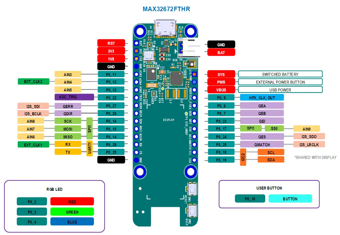
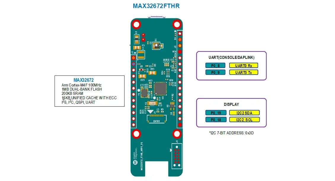
0.9 × 2.6 inch, FeatherWing-compatible
MAX8819 PMIC와 integrated charger
OLED, RGB LED, button, J9 16-pin + J7 12-pin
Part 2
접을 수 있는 영어 원문 전체
영어 원문 전체 펼치기
F01AB81461DE4CAE3432A190DFAF4478F6EB06F60D31932A6CBBF83D795E6156
.. _max32672_fthr:

MAX32672FTHR
############

Overview
********
The MAX32672FTHR is a rapid development platform that helps engineers quickly implement complex
sensor solutions using the MAX32672 Arm® Cortex®-M4. The board also includes the MAX8819 PMIC for
battery and power management. The form factor is a small, 0.9in by 2.6in, dual row header footprint
that is compatible with Adafruit® FeatherWing peripheral expansion boards. The board includes
an OLED display, a RGB indicator LED, and a user pushbutton. The MAX32672FTHR provides
a power-optimized flexible platform for quick proof-ofconcepts and early software development
to enhance time to market.

The Zephyr port is running on the MAX32672 MCU.

.. image:: ../../../../../../../boards/adi/max32672fthr/doc/img/max32672fthr_img1.webp
   :align: center
   :alt: MAX32672FTHR Front

.. image:: ../../../../../../../boards/adi/max32672fthr/doc/img/max32672fthr_img2.webp
   :align: center
   :alt: MAX32672FTHR Back

Hardware
********

- MAX32672 MCU:

  - High-Efficiency Microcontroller for Low-Power High-Reliability Devices

    - Arm Cortex-M4 Processor with FPU up to 100MHz
    - 1MB Dual-Bank Flash with Error Correction
    - 200KB SRAM (160KB with ECC Enabled), Optionally Preserved in Lowest Power Modes
    - EEPROM Emulation on Flash
    - 16KB Unified Cache with ECC
    - Resource Protection Unit (RPU) and MemoryProtection Unit (MPU)
    - Dual- or Single-Supply Operation, 1.7V to 3.6V
    - Wide Operating Temperature: -40°C to +105°C

  - Flexible Clocking Schemes

    - Internal High-Speed 100MHz Oscillator
    - Internal Low-Power 7.3728MHz and Ultra-Low-Power 80kHz Oscillators
    - 16MHz–32MHz Oscillator, 32.768kHz Oscillator(External Crystal Required)
    - External Clock Input for CPU, LPUART, LPTMR

  - Power Management Maximizes Uptime for Battery Applications

    - 59.8μA/MHz ACTIVE at 0.9V up to 12MHz(CoreMark®)
    - 56.6μA/MHz ACTIVE at 1.1V up to 100MHz(While(1))
    - 3.09μA Full Memory Retention Power in BACKUPMode at VDD = 1.8V
    - 350nA Ultra-Low-Power RTC at
    - Wake from LPUART or LPTMR

  - Optimal Peripheral Mix Provides Platform Scalability

    - Up to 42 General-Purpose I/O Pins
    - Up to Three SPI Master/Slave (up to 50Mbps)
    - Up to Three 4-Wire UART
    - Up to Three I2C Master/Slave 3.4Mbps High Speed
    - Up to Four 32-Bit Timers (TMR)
    - Up to Two Low-Power 32-Bit Timers (LPTMR)
    - One I2S Master/Slave for Digital Audio Interface
    - 12-Channel, 12-Bit, 1Msps SAR ADC with On-DieTemperature Sensor

  - Security and Integrity

    - Optional ECDSA-Based Cryptographic SecureBootloader in ROM
    - Secure Cryptographic Accelerator for Elliptic Curve
    - AES-128/192/256 Hardware Acceleration Engine

- Benefits and Features of MAX32672FTHR:

  - MAX8819 PMIC with Integrated Charger
  - On-Board DAPLink Debug and Programming Interface for Arm Cortex-M4
  - Breadboard-Compatible Headers
  - Micro USB Connector
  - RGB Indicator LED
  - User Pushbutton
  - OLED Display
  - SWD Debugger
  - Virtual UART Console

Supported Features
==================

Below interfaces are supported by Zephyr on MAX32672FTHR.

+-----------+------------+-------------------------------------+
| Interface | Controller | Driver/Component                    |
+===========+============+=====================================+
| NVIC      | on-chip    | nested vector interrupt controller  |
+-----------+------------+-------------------------------------+
| SYSTICK   | on-chip    | systick                             |
+-----------+------------+-------------------------------------+
| CLOCK     | on-chip    | clock and reset control             |
+-----------+------------+-------------------------------------+
| GPIO      | on-chip    | gpio                                |
+-----------+------------+-------------------------------------+
| UART      | on-chip    | serial                              |
+-----------+------------+-------------------------------------+


Connections and IOs
===================

J9 Pinout
**********

+---------+----------+-------------------------------------------------------------------------------------------------+
| Pin     | Name     | Description                                                                                     |
+=========+==========+=================================================================================================+
| 1       | RST      | Master Reset Signal                                                                             |
+---------+----------+-------------------------------------------------------------------------------------------------+
| 2       | 3V3      | 3.3V Output. Typically used to provide 3.3V to peripherals connected to the expansion headers.  |
+---------+----------+-------------------------------------------------------------------------------------------------+
| 3       | 1V8      | 1.8V Output. Typically used to provide 1.8V to peripherals connected to the expansion headers.  |
+---------+----------+-------------------------------------------------------------------------------------------------+
| 4       | GND      | Ground                                                                                          |
+---------+----------+-------------------------------------------------------------------------------------------------+
| 5       | P0_11    | GPIO or Analog Input (AIN3 channel).                                                            |
+---------+----------+-------------------------------------------------------------------------------------------------+
| 6       | P0_12    | GPIO or Analog Input (AIN4 channel).                                                            |
+---------+----------+-------------------------------------------------------------------------------------------------+
| 7       | P0_13    | GPIO or Analog Input (AIN5 channel).                                                            |
+---------+----------+-------------------------------------------------------------------------------------------------+
| 8       | P0_22    | GPIO or ADC_TRIG signal.                                                                        |
+---------+----------+-------------------------------------------------------------------------------------------------+
| 9       | P0_27    | GPIO or QERR signal.                                                                            |
+---------+----------+-------------------------------------------------------------------------------------------------+
| 10      | P0_26    | GPIO or QDIR signal.                                                                            |
+---------+----------+-------------------------------------------------------------------------------------------------+
| 11      | P0_16    | GPIO or SPI1 clock signal.                                                                      |
+---------+----------+-------------------------------------------------------------------------------------------------+
| 12      | P0_15    | GPIO or SPI1 MOSI signal.                                                                       |
+---------+----------+-------------------------------------------------------------------------------------------------+
| 13      | P0_14    | GPIO or SPI1 MISO signal.                                                                       |
+---------+----------+-------------------------------------------------------------------------------------------------+
| 14      | P0_28    | GPIO or UART1 Rx signal.                                                                        |
+---------+----------+-------------------------------------------------------------------------------------------------+
| 15      | P0_29    | GPIO or UART1 Tx signal.                                                                        |
+---------+----------+-------------------------------------------------------------------------------------------------+
| 16      | GND      | Ground                                                                                          |
+---------+----------+-------------------------------------------------------------------------------------------------+


J7 Pinout
**********

+---------+----------+-----------------------------------------------------------------------------------------------------------+
| Pin     | Name     | Description                                                                                               |
+=========+==========+===========================================================================================================+
| 1       | SYS      | SYS Switched Connection to the Battery. This is the primary system power supply and automatically         |
|         |          | switches between the battery voltage and the USB supply when available.                                   |
+---------+----------+-----------------------------------------------------------------------------------------------------------+
| 2       | PWR      | In battery-powered mode, turns off the PMIC if shorted to ground.                                         |
+---------+----------+-----------------------------------------------------------------------------------------------------------+
| 3       | VBUS     | USB VBUS Signal. This can be used as a 5V supply when connected to USB. This pin can also be              |
|         |          | used as an input to power the board.                                                                      |
+---------+----------+-----------------------------------------------------------------------------------------------------------+
| 4       | P0_5     | GPIO or HFX_CLK_OUT signal.                                                                               |
+---------+----------+-----------------------------------------------------------------------------------------------------------+
| 5       | P0_6     | GPIO or QEA signal.                                                                                       |
+---------+----------+-----------------------------------------------------------------------------------------------------------+
| 6       | P0_7     | GPIO or QEB signal.                                                                                       |
+---------+----------+-----------------------------------------------------------------------------------------------------------+
| 7       | P0_23    | GPIO or QEI signal.                                                                                       |
+---------+----------+-----------------------------------------------------------------------------------------------------------+
| 8       | P0_17    | GPIO or SPI1 slave select signal.                                                                         |
+---------+----------+-----------------------------------------------------------------------------------------------------------+
| 9       | P0_24    | GPIO or QES signal.                                                                                       |
+---------+----------+-----------------------------------------------------------------------------------------------------------+
| 10      | P0_25    | GPIO or QMATCH signal.                                                                                    |
+---------+----------+-----------------------------------------------------------------------------------------------------------+
| 11      | P0_18    | GPIO or I2C2 SCL signal.                                                                                  |
+---------+----------+-----------------------------------------------------------------------------------------------------------+
| 12      | P0_19    | GPIO or I2C2 SDA signal.                                                                                  |
+---------+----------+-----------------------------------------------------------------------------------------------------------+

Programming and Debugging
*************************

Flashing
========

The MAX32625 microcontroller on the board is flashed with DAPLink firmware at the factory.
It allows debugging and flashing the MAX32672 Arm Core over USB.

Once the debug probe is connected to your host computer, then you can simply run the
``west flash`` command to write a firmware image into flash.

Debugging
=========

Please refer to the `Flashing`_ section and run the ``west debug`` command
instead of ``west flash``.

References
**********

- `MAX32672FTHR web page`_

.. _MAX32672FTHR web page:
   https://www.analog.com/en/design-center/evaluation-hardware-and-software/evaluation-boards-kits/max32672fthr.html
Part 3
한국어 전문 번역
개요
MAX32672FTHR는 MAX32672 Arm Cortex-M4로 복잡한 sensor solution을 빠르게 구현하는 rapid-development platform입니다. MAX8819 PMIC가 battery와 power를 관리합니다. 0.9 × 2.6 inch dual-row header footprint는 Adafruit FeatherWing expansion board와 호환됩니다. OLED display, RGB indicator LED와 user pushbutton을 포함하며 proof-of-concept와 초기 software 개발 시간을 줄이는 power-optimized platform입니다.
Zephyr port는 MAX32672 MCU에서 실행됩니다.
하드웨어
MAX32672 MCU
- 고효율·고신뢰 저전력 MCU: 최대 100 MHz FPU 포함 Arm Cortex-M4, ECC가 있는 1 MB dual-bank flash, SRAM 200 KB(ECC 사용 시 160 KB), 최저 전력 mode에서 선택적 SRAM 보존, flash 기반 EEPROM emulation, ECC가 있는 16 KB unified cache, RPU(Resource Protection Unit)와 MPU, 1.7~3.6 V dual/single supply, -40~+105°C 동작.
- 유연한 clock: internal 100 MHz high-speed oscillator, 7.3728 MHz low-power oscillator, 80 kHz ultra-low-power oscillator, external crystal이 필요한 16~32 MHz 및 32.768 kHz oscillator, CPU·LPUART·LPTMR external clock input.
- 전력 관리: 0.9 V·12 MHz 이하 CoreMark에서 59.8 μA/MHz, 1.1 V·100 MHz 이하 while(1)에서 56.6 μA/MHz, VDD 1.8 V BACKUP mode의 full-memory retention 3.09 μA, ultra-low-power RTC 350 nA, LPUART 또는 LPTMR wake-up.
- Peripheral: GPIO 최대 42개, 50 Mbit/s SPI master/slave 최대 3개, 4-wire UART 최대 3개, 3.4 Mbit/s high-speed I2C master/slave 최대 3개, 32-bit timer 최대 4개, low-power 32-bit timer 최대 2개, digital audio용 I2S master/slave 1개, on-die temperature sensor가 있는 12-channel 12-bit 1 Msps SAR ADC.
- 보안과 무결성: ROM의 optional ECDSA secure bootloader, elliptic-curve secure cryptographic accelerator, AES-128/192/256 hardware engine.
MAX32672FTHR 기능
- integrated charger가 있는 MAX8819 PMIC
- on-board Cortex-M4 DAPLink debug/programming interface
- breadboard-compatible header와 Micro USB
- RGB LED, user pushbutton, OLED display
- SWD debugger와 virtual UART console
지원 기능
Zephyr는 다음 interface를 지원합니다.
| Interface | Controller | Driver/Component |
|---|---|---|
| NVIC | on-chip | nested vector interrupt controller |
| SYSTICK | on-chip | systick |
| CLOCK | on-chip | clock and reset control |
| GPIO | on-chip | gpio |
| UART | on-chip | serial |
연결과 I/O
J9 pinout
| Pin | Name | 설명 |
|---|---|---|
| 1 | RST | master reset signal |
| 2 | 3V3 | expansion header peripheral용 3.3 V output |
| 3 | 1V8 | expansion header peripheral용 1.8 V output |
| 4 | GND | ground |
| 5 | P0_11 | GPIO 또는 analog input AIN3 |
| 6 | P0_12 | GPIO 또는 analog input AIN4 |
| 7 | P0_13 | GPIO 또는 analog input AIN5 |
| 8 | P0_22 | GPIO 또는 ADC_TRIG |
| 9 | P0_27 | GPIO 또는 QERR |
| 10 | P0_26 | GPIO 또는 QDIR |
| 11 | P0_16 | GPIO 또는 SPI1 clock |
| 12 | P0_15 | GPIO 또는 SPI1 MOSI |
| 13 | P0_14 | GPIO 또는 SPI1 MISO |
| 14 | P0_28 | GPIO 또는 UART1 Rx |
| 15 | P0_29 | GPIO 또는 UART1 Tx |
| 16 | GND | ground |
J7 pinout
| Pin | Name | 설명 |
|---|---|---|
| 1 | SYS | battery switched connection. USB가 있으면 battery와 USB supply 사이를 자동 전환하는 primary system power |
| 2 | PWR | battery mode에서 ground에 short하면 PMIC off |
| 3 | VBUS | USB VBUS. USB 연결 시 5 V output 또는 board power input |
| 4 | P0_5 | GPIO 또는 HFX_CLK_OUT |
| 5 | P0_6 | GPIO 또는 QEA |
| 6 | P0_7 | GPIO 또는 QEB |
| 7 | P0_23 | GPIO 또는 QEI |
| 8 | P0_17 | GPIO 또는 SPI1 slave select |
| 9 | P0_24 | GPIO 또는 QES |
| 10 | P0_25 | GPIO 또는 QMATCH |
| 11 | P0_18 | GPIO 또는 I2C2 SCL |
| 12 | P0_19 | GPIO 또는 I2C2 SDA |
프로그래밍과 디버깅
on-board DAPLink를 사용합니다. board의 MAX32625 MCU에는 factory에서 DAPLink firmware가 기록되어 있어 USB를 통해 MAX32672 Arm core를 flash하고 debug합니다.
debug probe를 host computer에 연결한 뒤 다음 명령으로 firmware image를 flash에 기록합니다.
west flash디버깅
flash 절차와 같은 연결을 사용하되 west flash 대신 다음 명령을 실행합니다.
west debug참고 자료
Source
출처
영어 원문에는 문단, 문서 지시문, 표, 코드, 코드 심벌, 경로를 그대로 보존했습니다.