Part 1
요약·해설
MAX32655FTHR는 0.9 × 2.6 inch dual-row Feather Wing-compatible board입니다. MAX32655와 MAX20303 PMIC에 digital microphone, stereo codec, QSPI flash, microSD, RGB LED와 push button을 결합합니다.
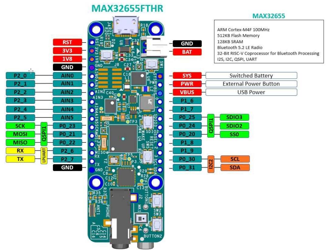
0.9 × 2.6 inch, Adafruit Feather Wing compatible
MAX20303 PMIC와 battery charger
push button 6개, RGB LED 3개
Part 2
접을 수 있는 영어 원문 전체
영어 원문 전체 펼치기
0508F1FB242A36D85EC0FFACFAE7E65FD16B1C0B3D2247A406A928BECF349C58
.. _max32655_fthr:
MAX32655FTHR
############
Overview
********
The MAX32655FTHR is a rapid development platform to help engineers quickly implement
ultra low-power wireless solutions using MAX32655 Arm© Cortex®-M4F and Bluetooth® 5.2 Low Energy (LE).
The board also includes the MAX20303 PMIC for battery and power management.
The form factor is a small 0.9in x 2.6in dual-row header footprint that is compatible
with Adafruit Feather Wing peripheral expansion boards. The board includes a variety of peripherals,
such as a digital microphone, lowpower stereo audio CODEC, 128MB QSPI Flash, micro SD card connector,
RGB indicator LED, and pushbutton.
The MAX32655FTHR provides a power-optimized flexible platform for quick proof-of-concepts and
early software development to enhance time to market. Go to
https://www.analog.com/MAX32655FTHR to get started developing with this board.
The Zephyr port is running on the MAX32655 MCU.
.. image:: ../../../../../../../boards/adi/max32655fthr/doc/img/max32655fthr_img1.jpg
:align: center
:alt: MAX32655FTHR Front
.. image:: ../../../../../../../boards/adi/max32655fthr/doc/img/max32655fthr_img2.jpg
:align: center
:alt: MAX32655FTHR Front Modules
.. image:: ../../../../../../../boards/adi/max32655fthr/doc/img/max32655fthr_img3.jpg
:align: center
:alt: MAX32655FTHR Back
Hardware
********
- MAX32655 MCU:
- Ultra-Low-Power Wireless Microcontroller
- Internal 100MHz Oscillator
- Flexible Low-Power Modes with 7.3728MHz System Clock Option
- 512KB Flash and 128KB SRAM (Optional ECC on One 32KB SRAM Bank)
- 16KB Instruction Cache
- Bluetooth 5.2 LE Radio
- Dedicated, Ultra-Low-Power, 32-Bit RISC-V Coprocessor to Offload Timing-Critical Bluetooth Processing
- Fully Open-Source Bluetooth 5.2 Stack Available
- Supports AoA, AoD, LE Audio, and Mesh
- High-Throughput (2Mbps) Mode
- Long-Range (125kbps and 500kbps) Modes
- Rx Sensitivity: -97.5dBm; Tx Power: +4.5dBm
- Single-Ended Antenna Connection (50Ω)
- Power Management Maximizes Battery Life
- 2.0V to 3.6V Supply Voltage Range
- Integrated SIMO Power Regulator
- Dynamic Voltage Scaling (DVS)
- 23.8μA/MHz Active Current at 3.0V
- 4.4μA at 3.0V Retention Current for 32KB
- Selectable SRAM Retention + RTC in Low-Power Modes
- Multiple Peripherals for System Control
- Up to Two High-Speed SPI Master/Slave
- Up to Three High-Speed I2C Master/Slave (3.4Mbps)
- Up to Four UART, One I2S Master/Slave
- Up to 8-Input, 10-Bit Sigma-Delta ADC 7.8ksps
- Up to Four Micro-Power Comparators
- Timers: Up to Two Four 32-Bit, Two LP, TwoWatchdog Timers
- 1-Wire® Master
- Up to Four Pulse Train (PWM) Engines
- RTC with Wake-Up Timer
- Up to 52 GPIOs
- Security and Integrity
- Available Secure Boot
- TRNG Seed Generator
- AES 128/192/256 Hardware Acceleration Engine
- External devices connected to the MAX32655FTHR:
- Audio Stereo Codec Interface
- Digital Microphone
- PMIC and Battery Charger
- A 128Mb QSPI flash
- Micro SDCard Interface
- RGB LEDs
- Push Buttons
Supported Features
==================
Below are the interfaces supported by Zephyr on MAX32655FTHR.
+-----------+------------+-------------------------------------+
| Interface | Controller | Driver/Component |
+===========+============+=====================================+
| NVIC | on-chip | nested vector interrupt controller |
+-----------+------------+-------------------------------------+
| SYSTICK | on-chip | systick |
+-----------+------------+-------------------------------------+
| CLOCK | on-chip | clock and reset control |
+-----------+------------+-------------------------------------+
| GPIO | on-chip | gpio |
+-----------+------------+-------------------------------------+
| UART | on-chip | serial |
+-----------+------------+-------------------------------------+
Push Buttons
************
There are six pushbuttons on the MAX32655FTHR board
SW1
===
PMIC Power Button, when the board is powered on state, pressing
this button for 12 seconds performs a hard powerdown.
When the board is in a powered-off state, pressing this button powers on the board.
This button can also be read by MAX32655 firmware, PMIC_PFN2 signal connected to Port 0.13
is a buffered input of the button status. When the button is pressed, this signal goes to a logic-low
state.
SW2
===
User-programmable function button connected to
MAX32655 Port 0.2 through a debouncer IC.
SW3
===
User-programmable function button connected to
MAX32655 Port 0.3 through a debouncer IC.
SW4
===
Wake-up button connected to MAX32655 Port 3.1.
SW5
===
Resets the MAX32655 through RSTN input of the MAX32655.
SW6
===
DAPLink adapter button. Keep this button
pressed while applying power to the board to
put the MAX32625 DAPLink adapter on board
to MAINTENANCE mode for DAPLink firmware
updates.
LEDs
****
There are three RGB LEDs on the MAX32655FTHR board
LED1 (D1)
=========
Connected to the MAX32655FTHR GPIO ports.
This LED can be controlled by user firmware.
Port 0.18: Red color
Port 0.19: Green color
Port 0.26: Blue color
LED2 (D2)
=========
Connected to MAX20303 PMIC LEDx outputs.
These LEDs can be controlled through I2C commands.
They also can be configured as charge
status indicators by issuing I2C commands.
LED3 (D3)
=========
DAPLink adapter MAX32625 status LED.
Controlled by the DAPLink adapter and cannot be
used as a user LED.
Programming and Debugging
*************************
Flashing
========
The MAX32625 microcontroller on the board is flashed with DAPLink firmware at the factory.
It allows debugging and flashing the MAX32655 Arm Core over USB.
Once the USB cable is connected to your host computer, then you can simply run the
``west flash`` command to write a firmware image into flash.
Debugging
=========
Please refer to the `Flashing`_ section and run the ``west debug`` command
instead of ``west flash``.
References
**********
- `MAX32655FTHR web page`_
.. _MAX32655FTHR web page:
https://www.analog.com/en/design-center/evaluation-hardware-and-software/evaluation-boards-kits/max32655fthr.html
Part 3
한국어 전문 번역
개요
MAX32655FTHR는 MAX32655 Arm Cortex-M4F와 Bluetooth 5.2 LE로 ultra-low-power wireless solution을 빠르게 구현하기 위한 development platform입니다. battery와 power management용 MAX20303 PMIC도 포함합니다.
0.9 × 2.6 inch dual-row header footprint는 Adafruit Feather Wing expansion board와 호환됩니다. digital microphone, low-power stereo audio codec, QSPI flash 128 MB, microSD connector, RGB indicator LED와 push button을 제공합니다. proof of concept와 초기 software 개발을 빠르게 진행하도록 power-optimized flexible platform을 제공합니다.
Zephyr port는 MAX32655 MCU에서 실행됩니다.
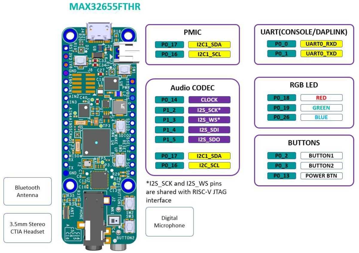
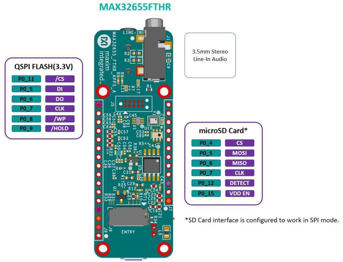
하드웨어
MAX32655 MCU
- Ultra-low-power wireless microcontroller: internal 100 MHz oscillator, 7.3728 MHz system clock 선택이 가능한 low-power mode, flash 512 KB, SRAM 128 KB(32 KB bank 하나에 optional ECC), instruction cache 16 KB.
- Bluetooth 5.2 LE radio: timing-critical Bluetooth 처리를 offload하는 ultra-low-power 32-bit RISC-V coprocessor, open-source Bluetooth 5.2 stack, AoA·AoD·LE Audio·Mesh, 2 Mbit/s high-throughput, 125/500 kbit/s long-range, RX sensitivity -97.5 dBm, TX power +4.5 dBm, 50 Ω single-ended antenna.
- Power management: 2.0~3.6 V supply, integrated SIMO regulator, DVS, 3.0 V에서 active current 23.8 μA/MHz, 32 KB retention current 4.4 μA, low-power mode의 선택적 SRAM retention과 RTC.
- Peripheral: high-speed SPI master/slave 최대 2개, 3.4 Mbit/s I2C master/slave 최대 3개, UART 최대 4개와 I2S master/slave 1개, input 8개의 10-bit sigma-delta ADC 7.8 ksps, micro-power comparator 최대 4개, 32-bit timer·low-power timer·watchdog timer, 1-Wire master, pulse-train PWM engine 최대 4개, wake-up timer를 갖춘 RTC, GPIO 최대 52개.
- Security: secure boot option, TRNG seed generator, AES-128/192/256 hardware acceleration.
MAX32655FTHR 외부 device
- audio stereo codec interface
- digital microphone
- PMIC와 battery charger
- QSPI flash 128 Mbit
- microSD card interface
- RGB LED
- push button
지원 기능
Zephyr는 MAX32655FTHR에서 다음 interface를 지원합니다.
| Interface | Controller | Driver/Component |
|---|---|---|
| NVIC | on-chip | nested vector interrupt controller |
| SYSTICK | on-chip | systick |
| CLOCK | on-chip | clock and reset control |
| GPIO | on-chip | gpio |
| UART | on-chip | serial |
Push button
MAX32655FTHR에는 push button이 6개 있습니다.
| Button | Function |
|---|---|
| SW1 | PMIC power button. powered-on 상태에서 12초 누르면 hard powerdown, powered-off 상태에서 누르면 power on. MAX32655 firmware도 읽을 수 있으며 P0.13의 PMIC_PFN2 buffered input은 button을 누르면 logic low. |
| SW2 | debouncer IC를 통해 MAX32655 P0.2에 연결된 user-programmable function button |
| SW3 | debouncer IC를 통해 MAX32655 P0.3에 연결된 user-programmable function button |
| SW4 | MAX32655 P3.1에 연결된 wake-up button |
| SW5 | MAX32655 RSTN input을 통한 reset |
| SW6 | DAPLink adapter button. power를 넣는 동안 누르면 on-board MAX32625 DAPLink adapter가 firmware update용 MAINTENANCE mode로 진입 |
LED
MAX32655FTHR에는 RGB LED가 3개 있습니다.
| LED | Connection and control |
|---|---|
| LED1 (D1) | MAX32655 GPIO에 연결되어 user firmware로 제어. P0.18 red, P0.19 green, P0.26 blue |
| LED2 (D2) | MAX20303 PMIC LEDx output에 연결. I2C command로 제어하거나 charge status indicator로 설정 |
| LED3 (D3) | DAPLink adapter MAX32625 status LED. DAPLink가 제어하므로 user LED로 사용할 수 없음 |
프로그래밍과 디버깅
on-board MAX32625 microcontroller에는 DAPLink firmware가 factory-programmed돼 있습니다. USB로 MAX32655 Arm core를 debug하고 flash할 수 있습니다. USB cable을 host에 연결한 뒤 west flash를 실행합니다.
Debugging
같은 연결에서 west flash 대신 west debug를 실행합니다.
참고 자료
Source
출처
영어 원문에는 문단, 문서 지시문, 표, 코드, 코드 심벌, 경로를 그대로 보존했습니다.