Part 1
요약·해설
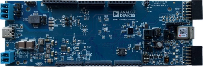
AD-APARD32690-SL은 intelligent·secure·connected field device prototype용 platform입니다. Arduino Mega-compatible header와 Pmod connector 두 개를 제공하며 Zephyr는 MAX32690 Cortex-M4F에서 실행됩니다.
120 MHz MAX32690 Cortex-M4F, internal flash 3 MB, SRAM 1 MB
MAXQ1065, ChipDNA PUF, secure boot·authentication
ADIN1110 10BASE-T1L 10 Mbit/s + SPoE support
Part 2
접을 수 있는 영어 원문 전체
영어 원문 전체 펼치기
4E623AFC2B163D6013B866BEEB5981F573F3F16A5DD4B7688BA0190C4F1D0F2F
.. _ad_apard32690_sl:

AD-APARD32690-SL
################

Overview
********
The AD-APARD32690-SL is a platform for prototyping intelligent, secure, and connected field devices.
It has an Arduino Mega-compatible form factor and two Pmod-compatible connectors.
The system includes the MAX32690 ARM Cortex-M4 with FPU-Based Microcontroller and Bluetooth LE 5.2.
The MCU is coupled with external RAM (2 x 512 Mb) and Flash (64 Mb) memories to meet the requirements
of the most demanding applications. The MAXQ1065 security coprocessor enables state of the art
security features such as for root-of-trust, mutual authentication, data confidentiality and
integrity, secure boot, and secure communications.
A 10 Mbps single-pair Ethernet link using the ADIN1110 10BASE-T1L MAC/PHY, enables remote
data acquisition and system configuration. The 10BASE-T1L interface also supports Single-pair
Power over Ethernet (SPoE) and be used for powering the system via an Arduino shield implementing
the required power circuitry.

The Zephyr port is running on the MAX32690 MCU.

.. image:: ../../../../../../../boards/adi/apard32690/doc/img/apard32690_img.webp
   :align: center
   :alt: AD-APARD32690-SL Front

Hardware
********

- MAX32690 MCU:

    - Ultra-Efficient Microcontroller for Battery-Powered Applications

      - 120MHz Arm Cortex-M4 Processor with FPU
      - 7.3728MHz and 60MHz Low-Power Oscillators
      - External Crystal Support (32MHz required for BLE)
      - 32.768kHz RTC Clock (Requires External Crystal)
      - 8kHz Always-On Ultra-Low Power Oscillator
      - 3MB Internal Flash, 1MB Internal SRAM (832kB ECC ON)
      - TBDμW/MHz Executing from Cache at 1.1V
      - 1.8V and 3.3V I/O with No Level Translators
      - External Flash & SRAM Expansion Interfaces

    - Bluetooth 5.2 LE Radio

      - Dedicated, Ultra-Low-Power, 32-Bit RISC-V Coprocessor to Offload Timing-Critical Bluetooth Processing
      - Fully Open-Source Bluetooth 5.2 Stack Available
      - Supports AoA, AoD, LE Audio, and Mesh
      - High-Throughput (2Mbps) Mode
      - Long-Range (125kbps and 500kbps) Modes
      - Rx Sensitivity: -97.5dBm; Tx Power: +4.5dBm
      - Single-Ended Antenna Connection (50Ω)

    - Multiple Peripherals for System Control

      - 16-Channel DMA
      - Up To Five Quad SPI Master (60MHz)/Slave (48MHz)
      - Up To Four 1Mbaud UARTs with Flow Control
      - Up To Two 1MHz I2C Master/Slave
      - I2S Master/Slave
      - Eight External Channel, 12-bit 1MSPS SAR ADC w/ on-die temperature sensor
      - USB 2.0 Hi-Speed Device
      - 16 Pulse Train Engines
      - Up To Six 32-Bit Timers with 8mA High Drive
      - Up To Two CAN 2.0 Controllers
      - Up To Four Micro-Power Comparators
      - 1-Wire Master

    - Security and Integrity

      - ChipDNA Physically Un-clonable Function (PUF)
      - Modular Arithmetic Accelerator (MAA), True Random Number Generator (TRNG)
      - Secure Nonvolatile Key Storage, SHA-256, AES-128/192/256
      - Secure Boot ROM

- External devices connected to the APARD32690:

  - On-Board HyperRAM
  - On-Board SPI Flash
  - USB 2.0 Type-C interface to the MAX32690
  - SPI PMOD connector
  - I2C PMOD connector
  - SWD 10-Pin Header
  - On-Board Bluetooth 5.2 LE Radio antenna
  - MAXQ1065 Ultralow Power Cryptographic Controller with ChipDNA
  - ADIN1110 Robust, Industrial, Low Power 10BASE-T1L Ethernet MAC-PHY
  - U-Blox NINA-W102 802.11b/g/n module with dual-mode Bluetooth v4.2
  - On-Board 5V, 3.3V, 1.8V, and 1.1V voltage regulators
  - 2-Pin external power supply terminal block (5V - 28V DC)
  - Board Power Provided by either the USB Port or the 2-Pin connector
  - Arduino Mega compatible header.
  - Two general-purpose LEDs and one general purpose push button.


Supported Features
==================

Below interfaces are supported by Zephyr on APARD32690.

+-----------+------------+------------------------------------+
| Interface | Controller | Driver/Component                   |
+===========+============+====================================+
| NVIC      | on-chip    | nested vector interrupt controller |
+-----------+------------+------------------------------------+
| SYSTICK   | on-chip    | systick                            |
+-----------+------------+------------------------------------+
| CLOCK     | on-chip    | clock and reset control            |
+-----------+------------+------------------------------------+
| GPIO      | on-chip    | gpio                               |
+-----------+------------+------------------------------------+
| UART      | on-chip    | serial                             |
+-----------+------------+------------------------------------+
| SPI       | on-chip    | spi                                |
+-----------+------------+------------------------------------+
| ADIN1110  | spi        | ADIN1110 10BASE-T1L mac/phy        |
+-----------+------------+------------------------------------+


Connections and IOs
===================

+-----------+---------------+---------------+--------------------------------------------------------------------------------------------------+
| Name      | Name          | Settings      | Description                                                                                      |
+===========+===============+===============+==================================================================================================+
| P55       | SWD TX        |               |                                                                                                  |
|           |               | +-----------+ |  +-------------------------------------------------------------------------------+               |
|           |               | | 1-2       | |  | Connects the SWD UART TX to the (UART) RX port of the U-Blox Nina W102.       |               |
|           |               | +-----------+ |  +-------------------------------------------------------------------------------+               |
|           |               | | 2-3       | |  | Connects the SWD UART TX to the UART0 TX pin of the MAX32690.                 |               |
|           |               | +-----------+ |  +-------------------------------------------------------------------------------+               |
|           |               |               |                                                                                                  |
+-----------+---------------+---------------+--------------------------------------------------------------------------------------------------+
| P50       | SWD RX        | +-----------+ |  +-------------------------------------------------------------------------------+               |
|           |               | | 1-2       | |  | Connects the SWD UART RX to the (UART) TX port of the U-Blox Nina W102.       |               |
|           |               | +-----------+ |  +-------------------------------------------------------------------------------+               |
|           |               | | 2-3       | |  | Connects the SWD UART RX to the UART0 RX pin of the MAX32690.                 |               |
|           |               | +-----------+ |  +-------------------------------------------------------------------------------+               |
|           |               |               |                                                                                                  |
+-----------+---------------+---------------+--------------------------------------------------------------------------------------------------+
| P51       | SWD POW       | +-----------+ |  +-------------------------------------------------------------------------------+               |
|           |               | | 1-2       | |  | Connects the SWD Vcc pin to 3.3V.                                             |               |
|           |               | +-----------+ |  +-------------------------------------------------------------------------------+               |
|           |               | | 2-3       | |  | Connects the SWD Vcc pin to 1.8V.                                             |               |
|           |               | +-----------+ |  +-------------------------------------------------------------------------------+               |
|           |               |               |                                                                                                  |
+-----------+---------------+---------------+--------------------------------------------------------------------------------------------------+
| P38       | UART RX WIFI  | +-----------+ |  +-------------------------------------------------------------------------------+               |
|           |               | | 1-2       | |  | Connect the U-Blox Nina W102 UART RX to the UART2A TX pin of the MAX32690     |               |
|           |               | +-----------+ |  +-------------------------------------------------------------------------------+               |
|           |               | | Open      | |  | Disconnects the U-Blox Nina W102 UART RX from the UART2A TX pin               |               |
|           |               | +-----------+ |  +-------------------------------------------------------------------------------+               |
|           |               |               |                                                                                                  |
+-----------+---------------+---------------+--------------------------------------------------------------------------------------------------+
| P58       | UART TX WIFI  | +-----------+ |  +-------------------------------------------------------------------------------+               |
|           |               | | 1-2       | |  | Connect the U-Blox Nina W102 UART TX to the UART2A RX pin of the MAX32690.    |               |
|           |               | +-----------+ |  +-------------------------------------------------------------------------------+               |
|           |               | | Open      | |  | Disconnects the U-Blox Nina W102 UART TX from the UART2A RX pin.              |               |
|           |               | +-----------+ |  +-------------------------------------------------------------------------------+               |
|           |               |               |                                                                                                  |
+-----------+---------------+---------------+--------------------------------------------------------------------------------------------------+
| S4        | SW1           | +-----------+ |  +-------------------------------------------------------------------------------+               |
|           |               | | On        | |  | Pulls the ADIN1110's SWPD_EN pin to 3.3V through a resistor.                  |               |
|           |               | +-----------+ |  +-------------------------------------------------------------------------------+               |
|           |               | | Off       | |  | Leaves the ADIN1110's SWPD_EN pin floating.                                   |               |
|           |               | +-----------+ |  +-------------------------------------------------------------------------------+               |
|           |               |               |                                                                                                  |
+-----------+---------------+---------------+--------------------------------------------------------------------------------------------------+
| S4        | SW2           | +-----------+ |  +-------------------------------------------------------------------------------+               |
|           |               | | On        | |  | Pulls the ADIN1110's CFG0 pin to 3.3V through a resistor.                     |               |
|           |               | +-----------+ |  +-------------------------------------------------------------------------------+               |
|           |               | | Off       | |  | Leaves the ADIN1110's CFG0 pin floating.                                      |               |
|           |               | +-----------+ |  +-------------------------------------------------------------------------------+               |
|           |               |               |                                                                                                  |
+-----------+---------------+---------------+--------------------------------------------------------------------------------------------------+
| S4        | SW3           | +-----------+ |  +-------------------------------------------------------------------------------+               |
|           |               | | On        | |  | Pulls the ADIN1110's CFG1 pin to 3.3V through a resistor.                     |               |
|           |               | +-----------+ |  +-------------------------------------------------------------------------------+               |
|           |               | | Off       | |  | Leaves the ADIN1110's CFG1 pin floating.                                      |               |
|           |               | +-----------+ |  +-------------------------------------------------------------------------------+               |
|           |               |               |                                                                                                  |
+-----------+---------------+---------------+--------------------------------------------------------------------------------------------------+


Programming and Debugging
*************************

Flashing
========

The MAX32690 MCU can be flashed by connecting an external debug probe to the
SWD port. SWD debug can be accessed through the Cortex 10-pin connector, P9.
Logic levels are either 1.8V or 3.3V (based on P51 selection).

Once the debug probe is connected to your host computer, then you can simply run the
``west flash`` command to write a firmware image into flash.

.. note::

   This board uses OpenOCD as the default debug interface. You can also use
   a Segger J-Link with Segger's native tooling by overriding the runner,
   appending ``--runner jlink`` to your ``west`` command(s). The J-Link should
   be connected to the standard 2*5 pin debug connector (P9) using an
   appropriate adapter board and cable.

Debugging
=========

Please refer to the `Flashing`_ section and run the ``west debug`` command
instead of ``west flash``.

References
**********

- `AD-APARD32690-SL web page`_

.. _AD-APARD32690-SL web page:
   https://www.analog.com/en/resources/evaluation-hardware-and-software/evaluation-boards-kits/ad-apard32690-sl.html
Part 3
한국어 전문 번역
개요
AD-APARD32690-SL은 intelligent, secure, connected field device를 prototype하기 위한 platform입니다. Arduino Mega-compatible form factor와 Pmod-compatible connector 두 개를 갖습니다.
system은 FPU가 있는 MAX32690 Arm Cortex-M4 microcontroller와 Bluetooth LE 5.2를 포함합니다. demanding application을 위해 external RAM 512 Mbit 두 개와 flash 64 Mbit가 연결됩니다. MAXQ1065 security coprocessor는 root of trust, mutual authentication, data confidentiality·integrity, secure boot와 secure communication 같은 보안 기능을 제공합니다.
ADIN1110 10BASE-T1L MAC-PHY를 사용하는 10 Mbit/s single-pair Ethernet link로 remote data acquisition과 system configuration이 가능합니다. 10BASE-T1L interface는 SPoE(Single-pair Power over Ethernet)도 지원하며 필요한 power circuit이 있는 Arduino shield를 통해 system 전원을 공급할 수 있습니다.
Zephyr port는 MAX32690 MCU에서 실행됩니다.
하드웨어
MAX32690 MCU
- 고효율 MCU: FPU가 있는 120 MHz Cortex-M4, 7.3728/60 MHz low-power oscillator, BLE에 필요한 32 MHz external crystal 지원, external crystal이 필요한 32.768 kHz RTC, always-on 8 kHz ultra-low-power oscillator, internal flash 3 MB, internal SRAM 1 MB(ECC 사용 시 832 KB), 1.8/3.3 V I/O, external flash·SRAM expansion interface.
- Bluetooth 5.2 LE: timing-critical Bluetooth 처리를 offload하는 32-bit RISC-V coprocessor, open-source stack, AoA·AoD·LE Audio·Mesh, 2 Mbit/s high-throughput, 125/500 kbit/s long-range, RX sensitivity -97.5 dBm, TX +4.5 dBm, 50 Ω antenna.
- System peripheral: 16-channel DMA, Quad SPI master/slave 최대 5개, flow control UART 최대 4개, 1 MHz I2C master/slave 최대 2개, I2S, 8-channel 12-bit 1 MSPS SAR ADC와 on-die temperature sensor, USB 2.0 high-speed device, pulse train engine 16개, 32-bit timer 최대 6개, CAN 2.0 최대 2개, micro-power comparator 최대 4개, 1-Wire master.
- Security: ChipDNA PUF, Modular Arithmetic Accelerator, TRNG, secure nonvolatile key storage, SHA-256, AES-128/192/256, secure boot ROM.
외부 device
- on-board HyperRAM과 SPI flash
- MAX32690용 USB 2.0 Type-C
- SPI Pmod와 I2C Pmod connector
- 10-pin SWD header와 Bluetooth 5.2 LE antenna
- ChipDNA를 갖춘 MAXQ1065 cryptographic controller
- ADIN1110 industrial low-power 10BASE-T1L Ethernet MAC-PHY
- dual-mode Bluetooth v4.2를 갖춘 U-Blox NINA-W102 802.11b/g/n module
- 5/3.3/1.8/1.1 V regulator
- 5~28 V DC external supply terminal block
- USB 또는 2-pin connector power
- Arduino Mega-compatible header
- general-purpose LED 두 개와 push button 하나
지원 기능
| Interface | Controller | Driver/Component |
|---|---|---|
| NVIC | on-chip | nested vector interrupt controller |
| SYSTICK | on-chip | systick |
| CLOCK | on-chip | clock and reset control |
| GPIO | on-chip | gpio |
| UART | on-chip | serial |
| SPI | on-chip | spi |
| ADIN1110 | spi | ADIN1110 10BASE-T1L mac/phy |
연결과 I/O
| Name | Signal | Setting | Description |
|---|---|---|---|
| P55 | SWD TX | 1-2 | SWD UART TX를 U-Blox NINA-W102 UART RX에 연결 |
| P55 | SWD TX | 2-3 | SWD UART TX를 MAX32690 UART0 TX에 연결 |
| P50 | SWD RX | 1-2 | SWD UART RX를 U-Blox NINA-W102 UART TX에 연결 |
| P50 | SWD RX | 2-3 | SWD UART RX를 MAX32690 UART0 RX에 연결 |
| P51 | SWD POW | 1-2 | SWD Vcc를 3.3 V에 연결 |
| P51 | SWD POW | 2-3 | SWD Vcc를 1.8 V에 연결 |
| P38 | UART RX WIFI | 1-2 | NINA-W102 UART RX를 MAX32690 UART2A TX에 연결 |
| P38 | UART RX WIFI | Open | 두 signal 연결 해제 |
| P58 | UART TX WIFI | 1-2 | NINA-W102 UART TX를 MAX32690 UART2A RX에 연결 |
| P58 | UART TX WIFI | Open | 두 signal 연결 해제 |
| S4 | SW1 | On | ADIN1110 SWPD_EN을 resistor를 통해 3.3 V로 pull-up |
| S4 | SW1 | Off | ADIN1110 SWPD_EN을 floating 상태로 둠 |
| S4 | SW2 | On | ADIN1110 CFG0을 resistor를 통해 3.3 V로 pull-up |
| S4 | SW2 | Off | ADIN1110 CFG0을 floating 상태로 둠 |
| S4 | SW3 | On | ADIN1110 CFG1을 resistor를 통해 3.3 V로 pull-up |
| S4 | SW3 | Off | ADIN1110 CFG1을 floating 상태로 둠 |
프로그래밍과 디버깅
MAX32690은 P9 Cortex 10-pin connector의 SWD port에 external debug probe를 연결해 flash할 수 있습니다. logic level은 P51 선택에 따라 1.8 V 또는 3.3 V입니다. probe를 host에 연결한 뒤 west flash를 실행합니다.
Debugging
같은 연결에서 west flash 대신 west debug를 실행합니다.
참고 자료
Source
출처
영어 원문에는 문단, 문서 지시문, 표, 코드, 코드 심벌, 경로를 그대로 보존했습니다.