Part 1
요약·해설
ItsyBitsy M4 Express는 36 × 18 mm 크기에 120 MHz Cortex-M4, SPI flash 2 MiB, GPIO 23개와 DotStar RGB LED를 담습니다. 일반 실행은 UF2 bootloader, debugging은 SWD probe를 이용합니다.
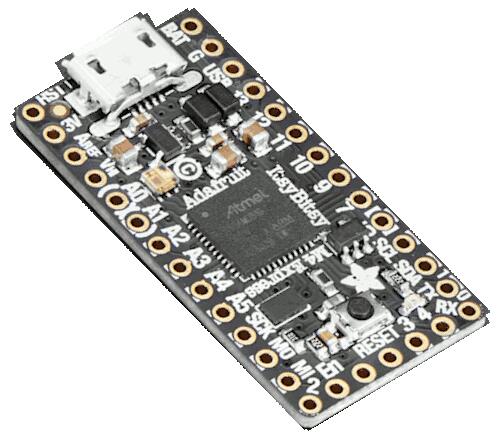
120 MHz ATSAMD51G19A Cortex-M4
flash 512 KiB, RAM 192 KiB, SPI flash 2 MiB
TCC_0 24-bit, 나머지 generator 16-bit
Part 2
접을 수 있는 영어 원문 전체
영어 원문 전체 펼치기
38C62B720CE63087A04D763F36DC99181858DB884F85CC1E52A4459DAF7C0CF2
.. _adafruit_itsybitsy_m4_express:

Adafruit ItsyBitsy M4 Express
#############################

Overview
********

The Adafruit ItsyBitsy M4 express is a small (36 mm x 18 mm) ARM development
board with an onboard RGB LED, USB port, 2 MiB of SPI flash, and range of I/O
broken out onto 23 GPIO pins.

.. image:: ../../../../../../../boards/adafruit/itsybitsy_m4_express/doc/img/adafruit_itsybitsy_m4_express.jpg
     :align: center
     :alt: Adafruit ItsyBitsy M4 Express

Hardware
********

- ATSAMD51G19A ARM Cortex-M4 processor at 120 MHz
- 512 KiB of flash memory and 192 KiB of RAM
- 2 MiB of SPI flash
- Internal trimmed 8 MHz oscillator
- A user LED
- An RGB DotStar LED
- Native USB port
- One reset button

Supported Features
==================

The adafruit_itsybitsy_m4_express board configuration supports the following
hardware features:

+-----------+------------+------------------------------------------+
| Interface | Controller | Driver/Component                         |
+===========+============+==========================================+
| NVIC      | on-chip    | Nested vector interrupt controller       |
+-----------+------------+------------------------------------------+
| SYSTICK   | on-chip    | systick                                  |
+-----------+------------+------------------------------------------+
| WDT       | on-chip    | Watchdog                                 |
+-----------+------------+------------------------------------------+
| GPIO      | on-chip    | I/O ports                                |
+-----------+------------+------------------------------------------+
| USART     | on-chip    | Serial ports                             |
+-----------+------------+------------------------------------------+
| SPI       | on-chip    | Serial Peripheral Interface ports        |
+-----------+------------+------------------------------------------+
| TRNG      | on-chip    | True Random Number Generator             |
+-----------+------------+------------------------------------------+
| HWINFO    | on-chip    | Unique 128 bit serial number             |
+-----------+------------+------------------------------------------+
| RTC       | on-chip    | Real-Time Counter                        |
+-----------+------------+------------------------------------------+
| USB       | on-chip    | USB device                               |
+-----------+------------+------------------------------------------+
| WDT       | on-chip    | Watchdog Timer                           |
+-----------+------------+------------------------------------------+
| PWM       | on-chip    | PWM                                      |
+-----------+------------+------------------------------------------+

Other hardware features are not currently supported by Zephyr.

The default configuration can be found in the Kconfig file
:zephyr_file:`boards/adafruit/itsybitsy_m4_express/adafruit_itsybitsy_m4_express_defconfig`.

Zephyr can use the default Cortex-M SYSTICK timer or the SAM0 specific RTC.
To use the RTC, set :code:`CONFIG_CORTEX_M_SYSTICK=n` and set
:code:`CONFIG_SYS_CLOCK_TICKS_PER_SEC` to no more than 32 kHZ divided by 7,
i.e. no more than 4500.

Connections and IOs
===================

The `Adafruit Learning System`_ has detailed information about
the board including `pinouts`_ and the `schematic`_.

System Clock
============

The SAMD51 MCU is configured to use the 32 kHz internal oscillator
with the on-chip PLL generating the 120 MHz system clock.

Serial Port
===========

The SAMD51 MCU has 6 SERCOM based USARTs.  On the ItsyBitsy, SERCOM3 is
the Zephyr console and is available on pins 0 (RX) and 1 (TX).

SPI Port
========

The SAMD51 MCU has 6 SERCOM based SPIs.  On the ItsyBitsy, SERCOM1 can be put
into SPI mode and used to connect to devices over the SCK (SCLK), MO (MOSI), and
MI (MISO) pins.

PWM
===

The SAMD51 has three PWM generators with up to six channels each.  :code:`TCC_0`
has a resolution of 24 bits and all other generators are 16 bit.  :code:`TCC_1`
pin 2 is mapped to PA18 (D7) and pin 3 is mapped to PA19 (D9).

USB Device Port
===============

The SAMD51 MCU has a USB device port that can be used to communicate
with a host PC.  See the :ref:`usb-samples` sample applications for
more, such as the :zephyr:code-sample:`usb-cdc-acm` sample which sets up a virtual
serial port that echos characters back to the host PC.

Programming and Debugging
*************************

The ItsyBitsy ships with a the BOSSA compatible UF2 bootloader.  The
bootloader can be entered by quickly tapping the reset button twice.

Additionally, if :code:`CONFIG_USB_CDC_ACM` is enabled then the bootloader
will be entered automatically when you run :code:`west flash`.

Flashing
========

#. Build the Zephyr kernel and the :ref:`hello_world` sample application:

   .. zephyr-app-commands::
      :zephyr-app: samples/hello_world
      :board: adafruit_itsybitsy_m4_express
      :goals: build
      :compact:

#. Connect the ItsyBitsy to your host computer using USB

#. Connect a 3.3 V USB to serial adapter to the board and to the
   host.  See the `Serial Port`_ section above for the board's pin
   connections.

#. Run your favorite terminal program to listen for output. Under Linux the
   terminal should be :code:`/dev/ttyUSB0`. For example:

   .. code-block:: console

      $ minicom -D /dev/ttyUSB0 -o

   The -o option tells minicom not to send the modem initialization
   string. Connection should be configured as follows:

   - Speed: 115200
   - Data: 8 bits
   - Parity: None
   - Stop bits: 1

#. Tap the reset button twice quickly to enter bootloader mode

#. Flash the image:

   .. zephyr-app-commands::
      :zephyr-app: samples/hello_world
      :board: adafruit_itsybitsy_m4_express
      :goals: flash
      :compact:

   You should see "Hello World! adafruit_itsybitsy_m4_express" in your terminal.

Debugging
=========

In addition to the built-in bootloader, the ItsyBitsy can be flashed and
debugged using a SWD probe such as the Segger J-Link.

#. Connect the board to the probe by connecting the :code:`SWCLK`,
   :code:`SWDIO`, :code:`RESET`, :code:`GND`, and :code:`3V3` pins on the
   ItsyBitsy to the :code:`SWCLK`, :code:`SWDIO`, :code:`RESET`, :code:`GND`,
   and :code:`VTref` pins on the `J-Link`_.

#. Flash the image:

   .. zephyr-app-commands::
      :zephyr-app: samples/hello_world
      :board: adafruit_itsybitsy_m4_express
      :goals: flash
      :flash-args: -r openocd
      :compact:

#. Start debugging:

   .. zephyr-app-commands::
      :zephyr-app: samples/hello_world
      :board: adafruit_itsybitsy_m4_express
      :goals: debug
      :compact:

References
**********

.. target-notes::

.. _Adafruit Learning System:
    https://learn.adafruit.com/introducing-adafruit-itsybitsy-m4

.. _pinouts:
    https://learn.adafruit.com/introducing-adafruit-itsybitsy-m4/pinouts

.. _schematic:
    https://learn.adafruit.com/introducing-adafruit-itsybitsy-m4/downloads

.. _J-Link:
    https://www.segger.com/products/debug-probes/j-link/technology/interface-description/
Part 3
한국어 전문 번역
개요
Adafruit ItsyBitsy M4 Express는 36 mm × 18 mm 크기의 소형 Arm development board입니다. on-board RGB LED, USB port, SPI flash 2 MiB와 GPIO pin 23개로 외부에 연결된 여러 I/O를 제공합니다.
하드웨어
- 120 MHz ATSAMD51G19A Arm Cortex-M4 processor
- flash memory 512 KiB, RAM 192 KiB
- SPI flash 2 MiB
- internal trimmed 8 MHz oscillator
- user LED
- RGB DotStar LED
- native USB port
- reset button 1개
지원 기능
adafruit_itsybitsy_m4_express board configuration은 다음 hardware 기능을 지원합니다.
| Interface | Controller | Driver/Component |
|---|---|---|
| NVIC | on-chip | Nested vector interrupt controller |
| SYSTICK | on-chip | systick |
| WDT | on-chip | Watchdog |
| GPIO | on-chip | I/O ports |
| USART | on-chip | Serial ports |
| SPI | on-chip | Serial Peripheral Interface ports |
| TRNG | on-chip | True Random Number Generator |
| HWINFO | on-chip | Unique 128 bit serial number |
| RTC | on-chip | Real-Time Counter |
| USB | on-chip | USB device |
| WDT | on-chip | Watchdog Timer |
| PWM | on-chip | PWM |
원문 표에는 WDT가 두 번 기재돼 있습니다. 그 밖의 hardware 기능은 현재 Zephyr에서 지원하지 않습니다. 기본 설정은 boards/adafruit/itsybitsy_m4_express/adafruit_itsybitsy_m4_express_defconfig에서 확인할 수 있습니다.
Zephyr는 기본 Cortex-M SYSTICK timer 또는 SAM0 전용 RTC를 사용할 수 있습니다. RTC를 사용하려면 CONFIG_CORTEX_M_SYSTICK=n으로 설정하고 CONFIG_SYS_CLOCK_TICKS_PER_SEC를 32 kHz를 7로 나눈 값, 즉 4,500 이하로 설정합니다.
연결과 I/O
Adafruit Learning System에서 pinout과 schematic을 확인할 수 있습니다.
System clock
SAMD51 MCU는 32 kHz internal oscillator를 사용하고 on-chip PLL로 120 MHz system clock을 생성합니다.
Serial port
SAMD51 MCU에는 SERCOM 기반 USART가 6개 있습니다. ItsyBitsy에서는 SERCOM3이 Zephyr console이며 pin 0(RX), pin 1(TX)에서 사용할 수 있습니다.
SPI port
SAMD51 MCU에는 SERCOM 기반 SPI가 6개 있습니다. SERCOM1을 SPI mode로 바꾸면 SCK(SCLK), MO(MOSI), MI(MISO) pin으로 device를 연결할 수 있습니다.
PWM
SAMD51에는 channel을 최대 6개씩 제공하는 PWM generator가 3개 있습니다. TCC_0의 resolution은 24-bit이고 나머지는 16-bit입니다. TCC_1 pin 2는 PA18(D7), pin 3은 PA19(D9)에 mapping됩니다.
USB device port
SAMD51 MCU의 USB device port는 host PC와 통신하는 데 사용할 수 있습니다. host에 character를 되돌려 보내는 virtual serial port를 구성하는 usb-cdc-acm sample 등을 참고합니다.
프로그래밍과 디버깅
ItsyBitsy에는 BOSSA-compatible UF2 bootloader가 설치돼 있습니다. reset button을 빠르게 두 번 누르면 진입합니다. CONFIG_USB_CDC_ACM이 enabled라면 west flash 실행 시 bootloader에 자동으로 진입합니다.
Flashing
hello_world를 build합니다.west build -b adafruit_itsybitsy_m4_express samples/hello_world- USB로 board를 host에 연결합니다.
- 3.3 V USB-to-serial adapter를 board와 host에 연결합니다.
Linux에서 보통
/dev/ttyUSB0을 엽니다.$ minicom -D /dev/ttyUSB0 -o-ooption은 minicom이 modem initialization string을 보내지 않게 합니다. 연결은 speed 115200, data 8 bit, parity none, stop bit 1로 설정합니다.- reset을 빠르게 두 번 눌러 bootloader mode로 진입합니다.
image를 flash합니다.
west flash
Hello World! adafruit_itsybitsy_m4_express가 terminal에 표시돼야 합니다.
Debugging
내장 bootloader 외에도 Segger J-Link 같은 SWD probe로 flash와 debug가 가능합니다.
- ItsyBitsy의
SWCLK,SWDIO,RESET,GND,3V3를 J-Link의SWCLK,SWDIO,RESET,GND,VTref에 각각 연결합니다. OpenOCD로 flash합니다.
west flash -r openocddebugging을 시작합니다.
west debug
참고 자료
Source
출처
영어 원문에는 문단, 문서 지시문, 표, 코드, 코드 심벌, 경로를 그대로 보존했습니다.