Part 1
요약·해설
이 보드는 Feather 표준 배치에 STM32F405 Cortex-M4F, USB-C, LiPo charger, microSD socket, 2 MB SPI flash를 결합합니다. Zephyr 3.7.0 보드 정의는 NVIC, SysTick, UART, GPIO, I2C, SPI, USB device를 활성화하며, 나머지 하드웨어는 아직 모두 활성화된 상태가 아닙니다.
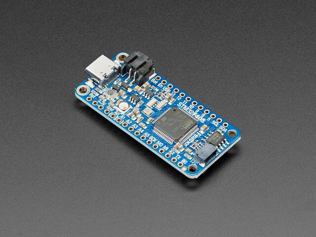
168 MHz STM32F405 Cortex-M4F, flash 1 MB
RAM 192 KB와 외부 SPI flash 2 MB
12 MHz HSE oscillator에서 168 MHz 생성
Part 2
접을 수 있는 영어 원문 전체
영어 원문 전체 펼치기
3D89BBB690AD00C51E5F7F7AF78291DDC416BB23B4791E38DDFD41DCCE5C6856
.. _adafruit_feather_stm32f405:

Adafruit Feather STM32F405 Express
##################################

Overview
********

The Adafruit Feather STM32F405 is an ARM Development board in the
Feather standard layout, sharing peripheral placement with other
devices labeled as Feathers or FeatherWings. The board is equipped
with a lithium ion battery charger, native USB C connector, 2MB of
external flash memory, and SD card socket.

.. image:: ../../../../../../../boards/adafruit/feather_stm32f405/doc/img/adafruit_feather_stm32f405.jpg
     :align: center
     :alt: Adafruit Feather STM32F405 Express

Hardware
********

- STM32F405 Cortex M4 with FPU and 1MB Flash, 168MHz speed
- 192KB RAM total - 128 KB RAM + 64 KB program-only/cache RAM
- USB C power and data
- LiPo connector and charger
- SD socket on the bottom, connected to SDIO port
- 2 MB SPI Flash chip
- Built in NeoPixel indicator
- I2C, UART, GPIO, ADCs, DACs
- Qwiic/STEMMA-QT connector for fast I2C connectivity
- SWD SMT mount region on board underside.

Supported Features
==================

The Adafruit Feather STM32F405 board configuration supports the
following hardware features:

+-----------+------------+----------------------+
| Interface | Controller | Driver/Component     |
+===========+============+======================+
| NVIC      | on-chip    | nested vectored      |
|           |            | interrupt controller |
+-----------+------------+----------------------+
| SYSTICK   | on-chip    | system clock         |
+-----------+------------+----------------------+
| UART      | on-chip    | serial port          |
+-----------+------------+----------------------+
| GPIO      | on-chip    | gpio                 |
+-----------+------------+----------------------+
| I2C       | on-chip    | i2c                  |
+-----------+------------+----------------------+
| SPI       | on-chip    | spi                  |
+-----------+------------+----------------------+
| USB       | on-chip    | USB device           |
+-----------+------------+----------------------+

Other hardware features have not been enabled yet for this board.

Connections and IOs
===================

The `Adafruit Feather STM32F405 Express Learn site`_ has detailed
information about the board including `pinouts`_ and the `schematic`_.

System Clock
============

The STM32F405 is configured to use the 12MHz HSE Oscillator to produce
a 168MHz system clock.

Serial Port
===========

The STM32F405 UART 3 peripheral is available on the TX (PB10) and RX
(PB11) pins.

I2C Port
========

The STM32F405 I2C1 peripheral is available on the SDA (PB7) and SCL
(PB6) pins.

SPI Port
========

The STM32F405 SPI2 peripheral is available on the SCK (PB13), MI
(PB14) and MO (PB15) pins.

SPI1 uses SCK (PB3), MI (PB4), MO (PB5) and SS (PA15) pins and is
dedicated to the 2 MB SPI Flash chip.

Programming and Debugging
*************************

DFU-Util programming is supported through Zephyr by default. Set up
of the built in DFU-Util bootloader is possible by following the
`instructions on the Learn website`_.

Flashing
========

#. Build the Zephyr kernel and the :zephyr:code-sample:`blinky` sample application:

   .. zephyr-app-commands::
      :zephyr-app: samples/basic/blinky
      :board: adafruit_feather_stm32f405
      :goals: build
      :compact:

#. On the Adafruit Feather STM32F405, connect the 3.3V pin to the B0 boot pin
   with a jumper wire.

#. Flash the image:

   .. zephyr-app-commands::
      :zephyr-app: samples/basic/blinky
      :board: adafruit_feather_stm32f405
      :goals: flash
      :compact:

   You should see the D13 LED blinking.

References
**********

.. target-notes::

.. _Adafruit Feather STM32F405 Express Learn site:
    https://learn.adafruit.com/adafruit-stm32f405-feather-express/

.. _pinouts:
    https://learn.adafruit.com/adafruit-stm32f405-feather-express/pinouts

.. _schematic:
    https://learn.adafruit.com/adafruit-stm32f405-feather-express/downloads

.. _instructions on the Learn website:
    https://learn.adafruit.com/adafruit-stm32f405-feather-express/dfu-bootloader-details
Part 3
한국어 전문 번역
개요
Adafruit Feather STM32F405는 Feather 표준 layout을 따르는 Arm 개발 보드로, Feather 또는 FeatherWing이라는 이름이 붙은 다른 장치와 peripheral 배치를 공유합니다. 이 보드에는 lithium-ion battery charger, native USB-C connector, 2 MB external flash memory, SD card socket이 있습니다.
하드웨어
- FPU와 1 MB flash를 갖춘 168 MHz STM32F405 Cortex-M4
- 총 192 KB RAM: 일반 RAM 128 KB와 program 전용/cache RAM 64 KB
- 전원과 data용 USB-C
- LiPo connector와 charger
- 보드 아래쪽의 SD socket, SDIO port 연결
- 2 MB SPI flash chip
- 내장 NeoPixel indicator
- I2C, UART, GPIO, ADC, DAC
- 빠른 I2C 연결용 Qwiic/STEMMA-QT connector
- 보드 아래쪽 SWD SMT mount 영역
지원 기능
Adafruit Feather STM32F405 보드 설정은 다음 하드웨어 기능을 지원합니다.
| Interface | Controller | Driver/Component |
|---|---|---|
| NVIC | on-chip | nested vectored interrupt controller |
| SYSTICK | on-chip | system clock |
| UART | on-chip | serial port |
| GPIO | on-chip | gpio |
| I2C | on-chip | i2c |
| SPI | on-chip | spi |
| USB | on-chip | USB device |
그 밖의 하드웨어 기능은 이 보드에서 아직 활성화되지 않았습니다.
연결과 I/O
Adafruit Feather STM32F405 Express Learn site에는 pinout과 schematic을 포함한 자세한 보드 정보가 있습니다.
System clock
STM32F405는 12 MHz HSE oscillator를 사용해 168 MHz system clock을 생성하도록 설정됩니다.
Serial port
STM32F405의 UART3 peripheral은 TX(PB10)와 RX(PB11) pin에서 사용할 수 있습니다.
I2C port
STM32F405의 I2C1 peripheral은 SDA(PB7)와 SCL(PB6) pin에서 사용할 수 있습니다.
SPI port
SPI2 peripheral은 SCK(PB13), MI(PB14), MO(PB15) pin에서 사용할 수 있습니다. SPI1은 SCK(PB3), MI(PB4), MO(PB5), SS(PA15) pin을 사용하며 2 MB SPI flash chip 전용입니다.
프로그래밍과 디버깅
Zephyr는 기본적으로 DFU-Util programming을 지원합니다. 내장 DFU-Util bootloader 설정은 Adafruit Learn website의 지침을 따릅니다.
Flashing
Zephyr kernel과
blinkysample application을 빌드합니다.west build -b adafruit_feather_stm32f405 samples/basic/blinkyAdafruit Feather STM32F405에서 3.3 V pin과
B0boot pin을 jumper wire로 연결합니다.image를 flash합니다.
west build -b adafruit_feather_stm32f405 samples/basic/blinky
west flash
D13 LED가 깜박여야 합니다.
참고 자료
- Adafruit Feather STM32F405 Express Learn site
- Pinouts
- Schematic
- DFU bootloader instructions
Source
출처
영어 원문에는 문단, 문서 지시문, 표, 코드, 코드 심벌, 경로를 그대로 보존했습니다.