Part 1
요약·해설
Icarus SoM DK는 nRF9160 SoM 평가와 개발을 위한 single-board kit입니다. USB-C, LED, reset/user button, battery charging port, external nano-SIM connector를 제공하며 Arduino Uno Rev3 shield도 연결할 수 있습니다.
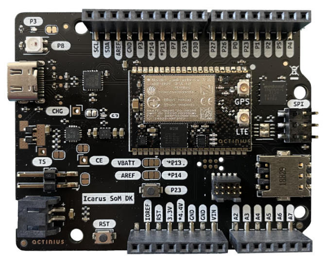
Arduino Uno Rev3 compatible shield headers
USB-C, VIN, LiPo charger와 3.3 V rail
SPI NOR, NeoPixel, blue LED, button, accelerometer
Part 2
접을 수 있는 영어 원문 전체
영어 원문 전체 펼치기
739AE538C0F777A88938BC87892D552627DCD91F86ECDECCC27DC598E3FEFE68
.. _actinius_icarus_som_dk:

Actinius Icarus SoM DK
######################

Overview
********

.. figure:: ../../../../../../../boards/actinius/icarus_som_dk/doc/img/icarus-som-dk.jpg
     :width: 450px
     :align: center
     :alt: Icarus SoM DK

     Icarus SoM Development Kit (nRF9160)

The Icarus SoM DK is a single board development kit for
evaluation and development on the Icarus SoM (`Icarus SoM Docs`_).
The Icarus SoM features the nRF9160 SiP from Nordic Semiconductor,
a low-power 3-axis accelerometer and an on-board eSIM.
The development kit provides interfacing to the SoM through USB-C,
a set of user LEDs, a reset and a user button, a battery charging port,
and a external nano SIM connector.
The board is also Arduino Uno Rev3 compatible which makes
using external shields possible.

The main uController is the Nordic Semiconductor nRF9160, with
ARM Cortex-M33F CPU, ARMv8-M Security Extension and the
following devices (provided directly by Nordic):

* :abbr:`ADC (Analog to Digital Converter)`
* CLOCK
* FLASH
* :abbr:`GPIO (General Purpose Input Output)`
* :abbr:`I2C (Inter-Integrated Circuit)`
* :abbr:`MPU (Memory Protection Unit)`
* :abbr:`NVIC (Nested Vectored Interrupt Controller)`
* :abbr:`PWM (Pulse Width Modulation)`
* :abbr:`RTC (nRF RTC System Clock)`
* Segger RTT (RTT Console)
* :abbr:`SPI (Serial Peripheral Interface)`
* :abbr:`UARTE (Universal asynchronous receiver-transmitter with EasyDMA)`
* :abbr:`WDT (Watchdog Timer)`
* :abbr:`IDAU (Implementation Defined Attribution Unit)`

.. figure:: ../../../../../../../boards/actinius/icarus_som_dk/doc/img/icarus-som-dk-block-diagram.jpg
     :width: 450px
     :align: center
     :alt: Icarus SoM DK Block Diagram

     Icarus SoM DK Block Diagram

Hardware
********

The detailed information about the on-board hardware can be found at the `Icarus SoM Product Website`_
and the `Icarus SoM DK Product Website`_.

Pin description
===============

External Pins available to user:

+----+-------+------------------------------------+------------------+
| #  | Label | Description                        | Device-tree node |
+====+=======+====================================+==================+
|  1 | NC    | Not Connected                      | -                |
+----+-------+------------------------------------+------------------+
|  2 | IOREF | I/O reference, connected to 3.3V   | -                |
+----+-------+------------------------------------+------------------+
|  3 | RST   | Reset of the nRF9160               | -                |
+----+-------+------------------------------------+------------------+
|  4 | 3.3V  | 3.3V Power output                  | -                |
+----+-------+------------------------------------+------------------+
|  5 | 4.4V  | Power output between Vbat and 4.4V | -                |
+----+-------+------------------------------------+------------------+
|  6 | GND   | Ground pin                         | -                |
+----+-------+------------------------------------+------------------+
|  7 | GND   | Ground pin                         | -                |
+----+-------+------------------------------------+------------------+
|  8 | VIN   | Power input pin (4.35V to 10.5V)   | -                |
+----+-------+------------------------------------+------------------+
|  9 | A2    | AIN2 / nRF9160 P0.15               | gpio0            |
+----+-------+------------------------------------+------------------+
| 10 | A3    | AIN3 / nRF9160 P0.16               | gpio0            |
+----+-------+------------------------------------+------------------+
| 11 | A4    | AIN4 / nRF9160 P0.17               | gpio0            |
+----+-------+------------------------------------+------------------+
| 12 | A5    | AIN5 / nRF9160 P0.18               | gpio0            |
+----+-------+------------------------------------+------------------+
| 13 | A6    | AIN6 / nRF9160 P0.19               | gpio0            |
+----+-------+------------------------------------+------------------+
| 14 | A7    | AIN7 / nRF9160 P0.20               | gpio0            |
+----+-------+------------------------------------+------------------+
| 15 | P4    | nRF9160 P0.04                      | gpio0            |
+----+-------+------------------------------------+------------------+
| 16 | P5    | nRF9160 P0.05                      | gpio0            |
+----+-------+------------------------------------+------------------+
| 17 | P2    | nRF9160 P0.02                      | gpio0            |
+----+-------+------------------------------------+------------------+
| 18 | P1    | nRF9160 P0.01                      | gpio0            |
+----+-------+------------------------------------+------------------+
| 19 | P23   | nRF9160 P0.23                      | gpio0            |
+----+-------+------------------------------------+------------------+
| 20 | P0    | nRF9160 P0.00                      | gpio0            |
+----+-------+------------------------------------+------------------+
| 21 | P26   | nRF9160 P0.26                      | gpio0            |
+----+-------+------------------------------------+------------------+
| 22 | P27   | nRF9160 P0.27                      | gpio0            |
+----+-------+------------------------------------+------------------+
| 23 | P30   | nRF9160 P0.30                      | gpio0            |
+----+-------+------------------------------------+------------------+
| 24 | P31   | nRF9160 P0.31                      | gpio0            |
+----+-------+------------------------------------+------------------+
| 25 | P7    | nRF9160 P0.07                      | gpio0            |
+----+-------+------------------------------------+------------------+
| 26 | P13   | nRF9160 P0.13 or NC (Jumper-dependent) | gpio0        |
+----+-------+------------------------------------+------------------+
| 27 | P14   | nRF9160 P0.14 or NC (Jumper-dependent) | gpio0        |
+----+-------+------------------------------------+------------------+
| 28 | P3    | nRF9160 P0.03                      | gpio0            |
+----+-------+------------------------------------+------------------+
| 29 | GND   | Ground pin                         | -                |
+----+-------+------------------------------------+------------------+
| 30 | AREF  | NC or AIN1 (Jumper-dependent)      | gpio0            |
+----+-------+------------------------------------+------------------+
| 31 | SDA   | I2C SDA pin                        | i2c2             |
+----+-------+------------------------------------+------------------+
| 32 | SCL   | I2C SCL pin                        | i2c2             |
+----+-------+------------------------------------+------------------+
|  - | TS    | Pin for optional battery thermistor| -                |
+----+-------+------------------------------------+------------------+
|  - | CHG   | Pin for battery charging indication| -                |
+----+-------+------------------------------------+------------------+
|  - | CE    | Pin for enabling/disabling charging| -                |
+----+-------+------------------------------------+------------------+


nRF9160 pins connected internally:

+--------------+------------------------------+---------------------+
| nRF9160 pin  | Function                     | Device-tree node    |
+==============+==============================+=====================+
| P0.03        | Blue LED                     | led0 / pwm-led0     |
+--------------+------------------------------+---------------------+
| P0.08        | NeoPixel RGB LED             | spi1                |
+--------------+------------------------------+---------------------+
| P0.12        | SIM select pin               | gpio0               |
+--------------+------------------------------+---------------------+
| P0.23        | Connected to the user button | gpio0 / button0     |
+--------------+------------------------------+---------------------+
| P0.24        | SPI NOR Flash chip select    | gpio0 / spi3        |
+--------------+------------------------------+---------------------+
| P0.28        | Accelerometer Interrupt 2    | lis2dh12-accel      |
+--------------+------------------------------+---------------------+
| P0.29        | Accelerometer Interrupt 1    | lis2dh12-accel      |
+--------------+------------------------------+---------------------+

Supported Features
==================

The actinius_icarus_som_dk board configuration supports the following
hardware features:

+-----------+------------+----------------------+
| Interface | Controller | Driver/Component     |
+===========+============+======================+
| ADC       | on-chip    | adc                  |
+-----------+------------+----------------------+
| CLOCK     | on-chip    | clock_control        |
+-----------+------------+----------------------+
| FLASH     | on-chip    | flash                |
+-----------+------------+----------------------+
| GPIO      | on-chip    | gpio                 |
+-----------+------------+----------------------+
| I2C(M)    | on-chip    | i2c                  |
+-----------+------------+----------------------+
| MPU       | on-chip    | arch/arm             |
+-----------+------------+----------------------+
| NVIC      | on-chip    | arch/arm             |
+-----------+------------+----------------------+
| PWM       | on-chip    | pwm                  |
+-----------+------------+----------------------+
| SPI(M/S)  | on-chip    | spi                  |
+-----------+------------+----------------------+
| SPU       | on-chip    | system protection    |
+-----------+------------+----------------------+
| UARTE     | on-chip    | serial               |
+-----------+------------+----------------------+
| ACCEL     | st         | lis2dh               |
+-----------+------------+----------------------+

SIM selection
*************

The sim choice (eSIM or nano-SIM) can be configured in Devicetree by adjusting
the ``sim`` property in the ``sim_select`` node.

Security components
===================

- Implementation Defined Attribution Unit (`IDAU`_).  The IDAU is implemented
  with the System Protection Unit and is used to define secure and non-secure
  memory maps.  By default, all of the memory space  (Flash, SRAM, and
  peripheral address space) is defined to be secure accessible only.
- Secure boot.

Building Secure/Non-Secure Zephyr applications
==============================================

The process requires the following steps:

1. Build the Secure Zephyr application using ``-DBOARD=actinius_icarus_som_dk``.
2. Build the Non-Secure Zephyr application using ``-DBOARD=actinius_icarus_som_dk/ns``.
3. Merge the two binaries together.

If you are using Segger Embedded Studio v4.18 or later, the two binaries are built, merged, and
burned automatically, unless you have disabled the feature.

When building a Secure/Non-Secure application, the Secure application will
have to set the IDAU (SPU) configuration to allow Non-Secure access to all
CPU resources utilized by the Non-Secure application firmware. SPU
configuration shall take place before jumping to the Non-Secure application.

More information can be found in the `Icarus SoM Product Website`_,
the `Icarus SoM DK Product Website`_ or the `Actinius Documentation Portal`_.

References
**********

.. target-notes::

.. _IDAU:
   https://developer.arm.com/docs/100690/latest/attribution-units-sau-and-idau

.. _Icarus SoM Product Website:
   https://www.actinius.com/icarus-som

.. _Icarus SoM DK Product Website:
   https://www.actinius.com/icarus-som-dk

.. _Icarus SoM Docs:
   https://docs.actinius.com/icarus-som/introduction

.. _Actinius Documentation Portal:
   https://docs.actinius.com
Part 3
한국어 전문 번역
개요
Icarus SoM DK는 Icarus SoM의 평가와 개발을 위한 single-board development kit입니다. Icarus SoM은 Nordic Semiconductor nRF9160 SiP, low-power 3-axis accelerometer와 on-board eSIM을 제공합니다. development kit는 USB-C, user LED, reset button과 user button, battery charging port, external nano-SIM connector를 통해 SoM에 연결할 수 있게 합니다. Arduino Uno Rev3와도 호환되므로 external shield를 사용할 수 있습니다.
main microcontroller는 Arm Cortex-M33F CPU와 Armv8-M Security Extension을 갖춘 Nordic Semiconductor nRF9160이며, Nordic가 직접 제공하는 장치는 다음과 같습니다.
- ADC(Analog to Digital Converter)
- CLOCK
- FLASH
- GPIO(General Purpose Input Output)
- I2C(Inter-Integrated Circuit)
- MPU(Memory Protection Unit)
- NVIC(Nested Vectored Interrupt Controller)
- PWM(Pulse Width Modulation)
- RTC(nRF RTC System Clock)
- Segger RTT(RTT console)
- SPI(Serial Peripheral Interface)
- EasyDMA를 갖춘 UARTE
- WDT(Watchdog Timer)
- IDAU(Implementation Defined Attribution Unit)
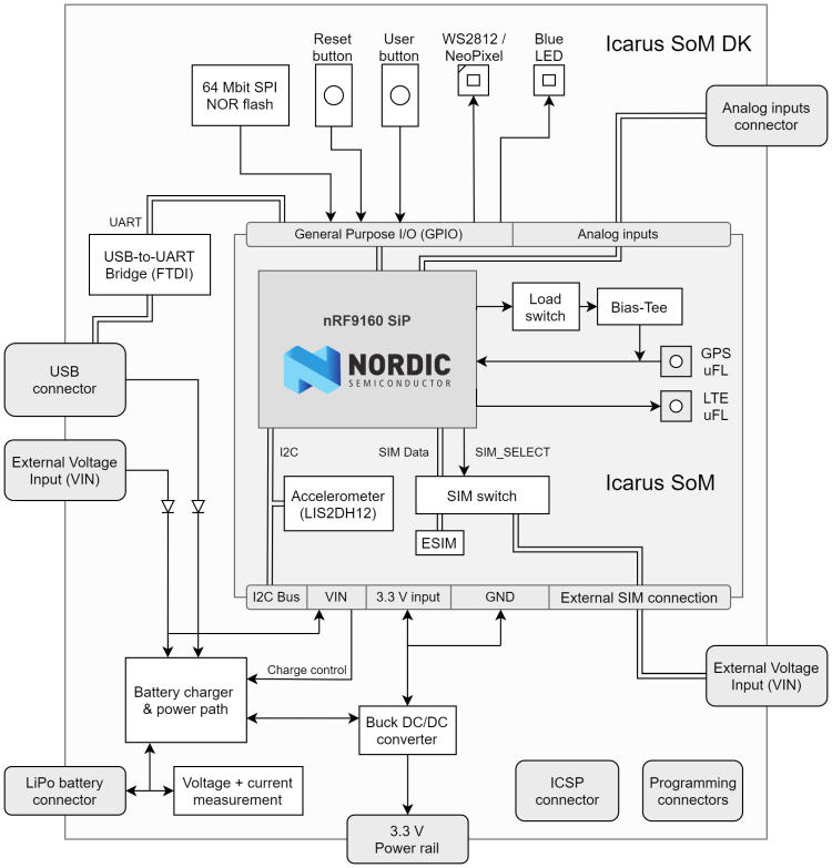
하드웨어
on-board hardware의 자세한 정보는 Icarus SoM product website와 Icarus SoM DK product website에서 확인할 수 있습니다.
사용자가 사용할 수 있는 외부 pin
| # | Label | Description | Device-tree node |
|---|---|---|---|
| 1 | NC | 연결되지 않음 | - |
| 2 | IOREF | 3.3 V에 연결된 I/O reference | - |
| 3 | RST | nRF9160 reset | - |
| 4 | 3.3V | 3.3 V power output | - |
| 5 | 4.4V | Vbat와 4.4 V 사이의 power output | - |
| 6 | GND | Ground pin | - |
| 7 | GND | Ground pin | - |
| 8 | VIN | power input pin, 4.35~10.5 V | - |
| 9 | A2 | AIN2 / nRF9160 P0.15 | gpio0 |
| 10 | A3 | AIN3 / nRF9160 P0.16 | gpio0 |
| 11 | A4 | AIN4 / nRF9160 P0.17 | gpio0 |
| 12 | A5 | AIN5 / nRF9160 P0.18 | gpio0 |
| 13 | A6 | AIN6 / nRF9160 P0.19 | gpio0 |
| 14 | A7 | AIN7 / nRF9160 P0.20 | gpio0 |
| 15 | P4 | nRF9160 P0.04 | gpio0 |
| 16 | P5 | nRF9160 P0.05 | gpio0 |
| 17 | P2 | nRF9160 P0.02 | gpio0 |
| 18 | P1 | nRF9160 P0.01 | gpio0 |
| 19 | P23 | nRF9160 P0.23 | gpio0 |
| 20 | P0 | nRF9160 P0.00 | gpio0 |
| 21 | P26 | nRF9160 P0.26 | gpio0 |
| 22 | P27 | nRF9160 P0.27 | gpio0 |
| 23 | P30 | nRF9160 P0.30 | gpio0 |
| 24 | P31 | nRF9160 P0.31 | gpio0 |
| 25 | P7 | nRF9160 P0.07 | gpio0 |
| 26 | P13 | nRF9160 P0.13 또는 NC, jumper에 따라 결정 | gpio0 |
| 27 | P14 | nRF9160 P0.14 또는 NC, jumper에 따라 결정 | gpio0 |
| 28 | P3 | nRF9160 P0.03 | gpio0 |
| 29 | GND | Ground pin | - |
| 30 | AREF | NC 또는 AIN1, jumper에 따라 결정 | gpio0 |
| 31 | SDA | I2C SDA pin | i2c2 |
| 32 | SCL | I2C SCL pin | i2c2 |
| - | TS | optional battery thermistor용 pin | - |
| - | CHG | battery charging indication pin | - |
| - | CE | charging enable/disable pin | - |
내부에 연결된 nRF9160 pin
| nRF9160 pin | Function | Device-tree node |
|---|---|---|
| P0.03 | Blue LED | led0 / pwm-led0 |
| P0.08 | NeoPixel RGB LED | spi1 |
| P0.12 | SIM select pin | gpio0 |
| P0.23 | user button에 연결 | gpio0 / button0 |
| P0.24 | SPI NOR flash chip select | gpio0 / spi3 |
| P0.28 | Accelerometer Interrupt 2 | lis2dh12-accel |
| P0.29 | Accelerometer Interrupt 1 | lis2dh12-accel |
지원 기능
actinius_icarus_som_dk board configuration은 다음 hardware 기능을 지원합니다.
| Interface | Controller | Driver/Component |
|---|---|---|
| ADC | on-chip | adc |
| CLOCK | on-chip | clock_control |
| FLASH | on-chip | flash |
| GPIO | on-chip | gpio |
| I2C(M) | on-chip | i2c |
| MPU | on-chip | arch/arm |
| NVIC | on-chip | arch/arm |
| PWM | on-chip | pwm |
| SPI(M/S) | on-chip | spi |
| SPU | on-chip | system protection |
| UARTE | on-chip | serial |
| ACCEL | st | lis2dh |
SIM 선택
eSIM 또는 nano-SIM 선택은 Devicetree의 sim_select node에 있는 sim property를 조정해 설정할 수 있습니다.
보안 구성요소
- IDAU(Implementation Defined Attribution Unit): System Protection Unit(SPU)로 구현되며 secure와 non-secure memory map을 정의합니다. 기본값에서는 flash, SRAM, peripheral address space를 포함한 전체 memory space에 secure access만 허용됩니다.
- Secure boot.
Secure/Non-Secure Zephyr application build
다음 순서가 필요합니다.
- Secure Zephyr application을
-DBOARD=actinius_icarus_som_dk로 build합니다. - Non-Secure Zephyr application을
-DBOARD=actinius_icarus_som_dk/ns로 build합니다. - 두 binary를 하나로 합칩니다.
Segger Embedded Studio v4.18 이상에서는 이 기능을 비활성화하지 않은 한 두 binary의 build, merge, burn이 자동으로 수행됩니다.
Secure/Non-Secure application을 만들 때 Secure application은 Non-Secure firmware가 사용하는 모든 CPU resource에 Non-Secure access를 허용하도록 IDAU(SPU)를 설정해야 합니다. SPU 설정은 Non-Secure application으로 jump하기 전에 끝나야 합니다.
자세한 정보는 Icarus SoM product website, Icarus SoM DK product website 또는 Actinius documentation portal에서 확인할 수 있습니다.
참고 자료
Source
출처
영어 원문에는 문단, 문서 지시문, 표, 코드, 코드 심벌, 경로를 그대로 보존했습니다.