Part 1
요약·해설
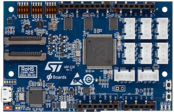
STM32 Sensor Mezzanine은 96Boards CE low-speed header, Arduino header, Grove connector를 STM32F446VE와 sensor에 연결하는 확장 보드입니다. AP 통신용 SPI slave, sensor용 SPI master, 외부 Grove SPI와 6개 PWM, digital microphone I2S까지 문서화돼 있습니다.
최대 180 MHz STM32F446VE Cortex-M4F, flash 512 KB, SRAM 128 KB
LPS22HB, LSM6DS3H, LIS3MDL, MP34DT01
96Boards LS, Arduino, Grove와 UART·I2C·SPI·PWM·I2S 연결
Part 2
접을 수 있는 영어 원문 전체
영어 원문 전체 펼치기
275AEEE227DC7046432F9CD789AC38C2C61A8A8B3C14377305435EF03121BC00
.. _96b_stm32_sensor_mez:

96Boards STM32 Sensor Mezzanine
###############################

Overview
********

96Boards STM32 Sensor Mezzanine is based on the ST Microelectronics
STM32F446VE Cortex M4 CPU.

This board acts as a mezzanine platform for all 96Boards CE compliant
boards. It can also be used as a standalone board.

.. figure:: ../../../../../../../boards/96boards/stm32_sensor_mez/doc/img/96b_stm32_sensor_mez.jpg
     :align: center
     :alt: 96Boards STM32 Sensor Mezzanine

     96Boards STM32 Sensor Mezzanine

Hardware
********

96Boards STM32 Sensor Mezzanine provides the following hardware components:

- STM32F446VE in LQFP100 package
- ARM |reg| 32-bit Cortex |reg|-M4 CPU with FPU
- 180 MHz max CPU frequency
- 1.8V work voltage
- 512 KB Flash
- 128 KB SRAM
- On board sensors:

  - Temperature/Pressure: STMicro LPS22HB
  - Accelerometer/Gyroscope: STMicro LSM6DS3H
  - Magnetometer: STMicro LIS3MDL
  - Microphone: STMicro MP34DT01

- 3User LEDs
- GPIO with external interrupt capability
- UART
- I2C (2)
- SPI (3)
- I2S (1)

Supported Features
==================

The Zephyr 96b_stm32_sensor_mez board configuration supports the following
hardware features:

+-----------+------------+-------------------------------------+
| Interface | Controller | Driver/Component                    |
+===========+============+=====================================+
| NVIC      | on-chip    | nested vector interrupt controller  |
+-----------+------------+-------------------------------------+
| SYSTICK   | on-chip    | system clock                        |
+-----------+------------+-------------------------------------+
| UART      | on-chip    | serial port                         |
+-----------+------------+-------------------------------------+
| GPIO      | on-chip    | gpio                                |
+-----------+------------+-------------------------------------+
| PINMUX    | on-chip    | pinmux                              |
+-----------+------------+-------------------------------------+
| FLASH     | on-chip    | flash                               |
+-----------+------------+-------------------------------------+
| SPI       | on-chip    | spi                                 |
+-----------+------------+-------------------------------------+
| I2C       | on-chip    | i2c                                 |
+-----------+------------+-------------------------------------+
| PWM       | on-chip    | pwm                                 |
+-----------+------------+-------------------------------------+
| I2S       | on-chip    | i2s                                 |
+-----------+------------+-------------------------------------+

The default board configuration can be found in
:zephyr_file:`boards/96boards/stm32_sensor_mez/96b_stm32_sensor_mez_defconfig`

Connections and IOs
===================

LED
---

- LED1 / User1 LED = PD10
- LED2 / User2 LED = PD11
- LED3 / User3 LED = PD12

Push buttons
------------

- BUTTON = RST (BT1)
- BUTTON = USR (BT2)

System Clock
============

96Boards STM32 Sensor Mezzanine can be driven by an internal oscillator as
well as the main PLL clock. In default board configuration, the 16MHz external
oscillator is used to drive the main PLL clock to generate a System Clock
(SYSCLK) at 84MHz. On the bus side, AHB/APB2 clocks runs at 84MHz, while APB1
clock runs at 42MHz.

Serial Port
===========

On 96Boards STM32 Sensor Mezzanine, Zephyr console output is assigned to UART4
exposed via on-board Micro USB connector. Default settings are 115200 8N1.

The default USART mappings for the remaining ones are:

- USART1: Connected to AP via UART0 on the 96Boards Low-Speed Header.
        - TX: PA9
        - RX: PA10

- USART2: Connected to D0(RX) and D1(TX) on the Arduino Header.
        - TX: PD5
        - RX: PD6

- USART3: Broken out to Grove connector J10.
        - TX: PD8
        - RX: PD9

I2C
---

96Boards STM32 Sensor Mezzanine board has up to 3 I2Cs. The default I2C
mapping is:

- I2C1_SCL  : PB6
- I2C1_SDA  : PB7
- I2C2_SCL  : PB10
- I2C2_SDA  : PC12

I2C2 goes to the Groove connectors and can be used to attach external sensors.

SPI
---
96Boards STM32 Sensor Mezzanine board has 3 SPIs. SPI1 is used in slave mode
as the communication bus with the AP. SPI2 is used in master mode to control
the LSM6DS3H sensor. SPI4 is broken out to Grove Connector J5.
The default SPI mapping is:

- SPI1_NSS  : PA4
- SPI1_SCK  : PA5
- SPI1_MISO : PA6
- SPI1_MOSI : PA7
- SPI2_NSS  : PB9
- SPI2_SCK  : PD3
- SPI2_MISO : PB14
- SPI2_MOSI : PB15
- SPI4_NSS  : PE11
- SPI4_SCK  : PE12
- SPI4_MISO : PE13
- SPI4_MOSI : PE14

PWM
---
96Boards STM32 Sensor Mezzanine board exposes 6 PWM channels on the Arduino
connector. The default PWM mapping is:

- PWM3_CH1  : PB4  : D9
- PWM3_CH3  : PC8  : D3
- PWM4_CH3  : PD14 : D6
- PWM4_CH4  : PD15 : D5
- PWM9_CH1  : PE5  : D12
- PWM9_CH2  : PE6  : D11

I2S
---

96Boards STM32 Sensor Mezzanine board exposes 1 I2S port which is connected
to the on-board ST MP34DT01 DMIC. The default I2S mapping is:

- I2S2_SD   : PC1
- I2S2_CK   : PC7

Programming and Debugging
*************************

Building
========

Here is an example for building the :ref:`hello_world` application.

.. zephyr-app-commands::
   :zephyr-app: samples/hello_world
   :board: 96b_stm32_sensor_mez
   :goals: build

Flashing
========

96Boards STM32 Sensor Mezzanine board includes an ST-LINK/V2-1 embedded
debug tool interface. This interface is supported by the openocd version
included in the Zephyr SDK.

Flashing an application to 96Boards STM32 Sensor Mezzanine
----------------------------------------------------------

Here is an example for the :ref:`hello_world` application.

Run a serial host program to connect with your 96Boards STM32 Sensor Mezzanine
board.

.. code-block:: console

   $ minicom -b 115200 -D /dev/ttyACM0

Build and flash the application:

.. zephyr-app-commands::
   :zephyr-app: samples/hello_world
   :board: 96b_stm32_sensor_mez
   :goals: build flash

You should see the following message on the console:

.. code-block:: console

   $ Hello World! 96b_stm32_sensor_mez

Debugging
=========

You can debug an application in the usual way.  Here is an example for the
:ref:`hello_world` application.

.. zephyr-app-commands::
   :zephyr-app: samples/hello_world
   :board: 96b_stm32_sensor_mez
   :maybe-skip-config:
   :goals: debug

References
**********

.. target-notes::

.. _96Boards STM32 Sensor Mezzanine website:
   https://www.96boards.org/documentation/mezzanine/stm32/

.. _STM32F446VE on www.st.com:
   https://www.st.com/en/microcontrollers/stm32f446ve.html

.. _STM32F446 reference manual:
   https://www.st.com/resource/en/reference_manual/dm00135183.pdf
Part 3
한국어 전문 번역
개요
96Boards STM32 Sensor Mezzanine은 STMicroelectronics STM32F446VE Cortex-M4 CPU 기반입니다. 모든 96Boards CE compliant board의 mezzanine platform으로 동작하며 독립형 보드로도 사용할 수 있습니다.
하드웨어
- LQFP100 package STM32F446VE
- FPU를 갖춘 Arm 32-bit Cortex-M4, 최대 180 MHz
- 동작 전압 1.8 V, flash 512 KB, SRAM 128 KB
- 내장 sensor: LPS22HB 온도/압력, LSM6DS3H accelerometer/gyroscope, LIS3MDL magnetometer, MP34DT01 microphone
- user LED 3개
- 외부 interrupt 가능한 GPIO
- UART, I2C 2개, SPI 3개, I2S 1개
지원 기능
| Interface | Controller | Driver/Component |
|---|---|---|
| NVIC | on-chip | nested vector interrupt controller |
| SYSTICK | on-chip | system clock |
| UART | on-chip | serial port |
| GPIO | on-chip | gpio |
| PINMUX | on-chip | pinmux |
| FLASH | on-chip | flash |
| SPI | on-chip | spi |
| I2C | on-chip | i2c |
| PWM | on-chip | pwm |
| I2S | on-chip | i2s |
기본 설정 파일은 boards/96boards/stm32_sensor_mez/96b_stm32_sensor_mez_defconfig입니다.
연결과 I/O
LED
LED1 / User1 LED = PD10LED2 / User2 LED = PD11LED3 / User3 LED = PD12
Push button
BUTTON = RST (BT1)BUTTON = USR (BT2)
System clock
internal oscillator 또는 main PLL clock으로 구동할 수 있습니다. 기본 설정에서는 16 MHz external oscillator가 main PLL을 구동해 84 MHz SYSCLK을 생성합니다. AHB/APB2는 84 MHz, APB1은 42 MHz입니다.
Serial port
Zephyr console은 on-board Micro-USB connector에 노출된 UART4에 할당되며 기본 설정은 115200 8N1입니다. 나머지 USART의 기본 mapping은 다음과 같습니다.
- USART1: 96Boards Low-Speed Header의 UART0을 통해 AP에 연결, TX
PA9, RXPA10 - USART2: Arduino Header D0(RX), D1(TX), TX
PD5, RXPD6 - USART3: Grove connector J10, TX
PD8, RXPD9
I2C
원문은 보드가 최대 3개의 I2C를 가진다고 설명하며 다음 기본 mapping을 제시합니다.
I2C1_SCL: PB6I2C1_SDA: PB7I2C2_SCL: PB10I2C2_SDA: PC12
I2C2는 원문 표기의 Groove connector로 연결되어 외부 sensor를 부착할 수 있습니다.
SPI
SPI는 3개입니다. SPI1은 AP 통신 bus의 slave mode, SPI2는 LSM6DS3H를 제어하는 master mode, SPI4는 Grove connector J5에 사용됩니다.
SPI1_NSS: PA4SPI1_SCK: PA5SPI1_MISO: PA6SPI1_MOSI: PA7SPI2_NSS: PB9SPI2_SCK: PD3SPI2_MISO: PB14SPI2_MOSI: PB15SPI4_NSS: PE11SPI4_SCK: PE12SPI4_MISO: PE13SPI4_MOSI: PE14
PWM
Arduino connector에 PWM channel 6개를 노출합니다.
PWM3_CH1: PB4: D9PWM3_CH3: PC8: D3PWM4_CH3: PD14: D6PWM4_CH4: PD15: D5PWM9_CH1: PE5: D12PWM9_CH2: PE6: D11
I2S
on-board ST MP34DT01 digital microphone에 연결된 I2S port 하나를 노출합니다. 기본 mapping은 I2S2_SD: PC1, I2S2_CK: PC7입니다.
프로그래밍과 디버깅
빌드
hello_world 빌드 예는 다음과 같습니다.
# Zephyr 저장소 루트에서
west build -b 96b_stm32_sensor_mez samples/hello_world
Flashing
보드에는 ST-LINK/V2-1 embedded debug interface가 포함되며 Zephyr SDK에 포함된 OpenOCD가 이를 지원합니다.
serial host program으로 보드에 연결합니다.
$ minicom -b 115200 -D /dev/ttyACM0애플리케이션을 빌드하고 flash합니다.
# Zephyr 저장소 루트에서
west build -b 96b_stm32_sensor_mez samples/hello_world
west flash
console에 다음 메시지가 보여야 합니다.
$ Hello World! 96b_stm32_sensor_mezDebugging
일반적인 방식으로 debug할 수 있습니다.
# Zephyr 저장소 루트에서
west build -b 96b_stm32_sensor_mez samples/hello_world
west debug
참고 자료
- 96Boards STM32 Sensor Mezzanine website
- STM32F446VE product page
- STM32F446 reference manual
Source
출처
영어 원문에는 문단, 문서 지시문, 표, 코드, 코드 심벌, 경로를 그대로 보존했습니다.