Part 1
요약·해설
Meerkat96은 Linux용 dual Cortex-A7과 real-time 처리를 위한 Cortex-M4를 결합한 i.MX7D board입니다. M4에는 독립 QSPI flash가 없으므로 A7의 U-Boot 또는 Linux가 Zephyr image를 RAM에 복사하고 PC·SP와 reset 상태를 설정해야 합니다.
dual Cortex-A7 800 MHz/1 GHz + Cortex-M4 200 MHz
TCML·TCMU·OCRAM·OCRAM_S·DDR 중 build 시 선택
A7 U-Boot bootaux 또는 J-Link로 PC·SP·reset 제어
Part 2
접을 수 있는 영어 원문 전체
영어 원문 전체 펼치기
9F986E3766405A8049F967090696B6F5433CABFFD9DA8BC727FDFE8E30A65A7E
.. _96b_meerkat96:

96Boards Meerkat96
##################

Overview
********

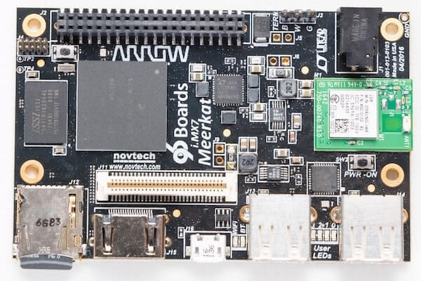
96Boards Meerkat96 board is based on NXP i.MX7 Hybrid multi-core processor,
composed of a dual Cortex®-A7 and a single Cortex®-M4 core.
Zephyr OS is ported to run on the Cortex®-M4 core.

- Board features:

  - RAM: 512 Mbyte
  - Storage:

    - microSD Socket
  - Wireless:

    - WiFi: 2.4GHz IEEE 802.11b/g/n
    - Bluetooth: v4.1 (BR/EDR)
  - USB:

    - Host - 2x type A
    - OTG: - 1x type micro-B
  - HDMI
  - Connectors:

    - 40-Pin Low Speed Header
    - 60-Pin High Speed Header
  - LEDs:

    - 4x Green user LEDs
    - 1x Blue Bluetooth LED
    - 1x Yellow WiFi LED

.. image:: ../../../../../../../boards/96boards/meerkat96/doc/img/96b_meerkat96.jpg
   :align: center
   :alt: 96Boards Meerkat96

More information about the board can be found at the
`96Boards website`_.

Hardware
********

The i.MX7 SoC provides the following hardware capabilities:

- Dual Cortex A7 (800MHz/1.0GHz) core and Single Cortex M4 (200MHz) core

- Memory

  - External DDR memory up to 1 Gbyte
  - Internal RAM -> A7: 256KB SRAM
  - Internal RAM -> M4: 3x32KB (TCML, TCMU, OCRAM_S), 1x128KB (OCRAM) and 1x256MB (DDR)

- Display

  - RGB 1920x1080x24bpp
  - 4-wire Resistive touch

- Multimedia

  - 1x Camera Parallel Interface
  - 1x Analog Audio Line in (Stereo)
  - 1x Analog Audio Mic in (Mono)
  - 1x Analog Audio Headphone out (Stereo)

- Connectivity

  - USB 2.0 OTG (High Speed)
  - USB 2.0 host (High Speed)
  - 10/100 Mbit/s Ethernet PHY
  - 4x I2C
  - 4x SPI
  - 7x UART
  - 1x IrDA
  - 20x PWM
  - Up to 125 GPIO
  - 4x Analog Input (12 Bit)
  - 2x SDIO/SD/MMC (8 Bit)
  - 2x CAN

More information about the i.MX7 SoC can be found here:

- `i.MX 7 Series Website`_
- `i.MX 7 Dual Datasheet`_
- `i.MX 7 Dual Reference Manual`_

Supported Features
==================

The Zephyr 96b_meerkat96 board configuration supports the following hardware
features:

+-----------+------------+-------------------------------------+
| Interface | Controller | Driver/Component                    |
+===========+============+=====================================+
| NVIC      | on-chip    | nested vector interrupt controller  |
+-----------+------------+-------------------------------------+
| SYSTICK   | on-chip    | systick                             |
+-----------+------------+-------------------------------------+
| GPIO      | on-chip    | gpio                                |
+-----------+------------+-------------------------------------+
| UART      | on-chip    | serial port-polling;                |
|           |            | serial port-interrupt               |
+-----------+------------+-------------------------------------+

The default configuration can be found in the defconfig file:

	:zephyr_file:`boards/96boards/meerkat96/96b_meerkat96_mcimx7d_m4_defconfig`

Other hardware features are not currently supported by the port.

Connections and IOs
===================

96Boards Meerkat96 board was tested with the following pinmux controller
configuration.

+---------------+-----------------+---------------------------+
| Board Name    | SoC Name        | Usage                     |
+===============+=================+===========================+
| UART_1 RXD    | UART1_TXD       | UART Console              |
+---------------+-----------------+---------------------------+
| UART_1 TXD    | UART1_RXD       | UART Console              |
+---------------+-----------------+---------------------------+
| LED_R1        | GPIO1_IO04      | LED0                      |
+---------------+-----------------+---------------------------+
| LED_R2        | GPIO1_IO05      | LED1                      |
+---------------+-----------------+---------------------------+
| LED_R3        | GPIO1_IO06      | LED2                      |
+---------------+-----------------+---------------------------+
| LED_R4        | GPIO1_IO07      | LED3                      |
+---------------+-----------------+---------------------------+

System Clock
============

The M4 Core is configured to run at a 200 MHz clock speed.

Serial Port
===========

The iMX7D SoC has seven UARTs. UART_1 is configured for the console and
the remaining are not used/tested.

Programming and Debugging
*************************

The 96Boards Meerkat96 board doesn't have QSPI flash for the M4 and it needs
to be started by the A7 core. The A7 core is responsible to load the M4 binary
application into the RAM, put the M4 in reset, set the M4 Program Counter and
Stack Pointer, and get the M4 out of reset. The A7 can perform these steps at
bootloader level or after the Linux system has booted.

The M4 can use up to 5 different RAMs. These are the memory mapping for A7 and M4:

+------------+-----------------------+------------------------+-----------------------+----------------------+
| Region     | Cortex-A7             | Cortex-M4 (System Bus) | Cortex-M4 (Code Bus)  | Size                 |
+============+=======================+========================+=======================+======================+
| DDR        | 0x80000000-0xFFFFFFFF | 0x80000000-0xDFFFFFFF  | 0x10000000-0x1FFEFFFF | 2048MB (less for M4) |
+------------+-----------------------+------------------------+-----------------------+----------------------+
| OCRAM      | 0x00900000-0x0091FFFF | 0x20200000-0x2021FFFF  | 0x00900000-0x0091FFFF | 128KB                |
+------------+-----------------------+------------------------+-----------------------+----------------------+
| TCMU       | 0x00800000-0x00807FFF | 0x20000000-0x20007FFF  |                       | 32KB                 |
+------------+-----------------------+------------------------+-----------------------+----------------------+
| TCML       | 0x007F8000-0x007FFFFF |                        | 0x1FFF8000-0x1FFFFFFF | 32KB                 |
+------------+-----------------------+------------------------+-----------------------+----------------------+
| OCRAM_S    | 0x00180000-0x00187FFF | 0x20180000-0x20187FFF  | 0x00000000-0x00007FFF | 32KB                 |
+------------+-----------------------+------------------------+-----------------------+----------------------+
| QSPI Flash |                       |                        | 0x08000000-0x0BFFFFFF | 64MB                 |
+------------+-----------------------+------------------------+-----------------------+----------------------+

For more information about memory mapping see the
`i.MX 7 Dual Reference Manual`_  (section 2.1.2 and 2.1.3), and the
`Toradex Wiki`_.

At compilation time you have to choose which RAM will be used. This
configuration is done in the file :zephyr_file:`boards/96boards/meerkat96/96b_meerkat96_mcimx7d_m4.dts`
with "zephyr,flash" (when CONFIG_XIP=y) and "zephyr,sram" properties.
The available configurations are:

.. code-block:: none

   "zephyr,flash"
   - &ddr_code
   - &tcml_code
   - &ocram_code
   - &ocram_s_code
   - &ocram_pxp_code
   - &ocram_epdc_code

   "zephyr,sram"
   - &ddr_sys
   - &tcmu_sys
   - &ocram_sys
   - &ocram_s_sys
   - &ocram_pxp_sys
   - &ocram_epdc_sys


Below you will find the instructions to load and run Zephyr on M4 from
A7 using u-boot.

Copy the compiled zephyr.bin to the first FAT partition of the SD card and
plug into the board. Power it up and stop the u-boot execution.
Set the u-boot environment variables and run the zephyr.bin from the
appropriated memory configured in the Zephyr compilation:

.. code-block:: console

   setenv bootm4 'fatload mmc 0:1 $m4addr $m4fw && dcache flush && bootaux $m4addr'
   # TCML
   setenv m4tcml 'setenv m4fw zephyr.bin; setenv m4addr 0x007F8000'
   setenv bootm4tcml 'run m4tcml && run bootm4'
   run bootm4tcml
   # TCMU
   setenv m4tcmu 'setenv m4fw zephyr.bin; setenv m4addr 0x00800000'
   setenv bootm4tcmu 'run m4tcmu && run bootm4'
   run bootm4tcmu
   # OCRAM
   setenv m4ocram 'setenv m4fw zephyr.bin; setenv m4addr 0x00900000'
   setenv bootm4ocram 'run m4ocram && run bootm4'
   run bootm4ocram
   # OCRAM_S
   setenv m4ocrams 'setenv m4fw zephyr.bin; setenv m4addr 0x00180000'
   setenv bootm4ocrams 'run m4ocrams && run bootm4'
   run bootm4ocrams
   # DDR
   setenv m4ddr 'setenv m4fw zephyr.bin; setenv m4addr 0x80000000'
   setenv bootm4ddr 'run m4ddr && run bootm4'
   run bootm4ddr

Debugging
=========

96Boards Meerkat96 board can be debugged by connecting an external JLink
JTAG debugger to the J4 debug connector. Then download and install
`J-Link Tools`_ and `NXP iMX7D Connect CortexM4.JLinkScript`_.

To run Zephyr Binary using J-Link create the following script in order to
get the Program Counter and Stack Pointer from zephyr.bin.

get-pc-sp.sh:
.. code-block:: console

   #!/bin/sh

   firmware=$1

   pc=$(od -An -N 8 -t x4 $firmware | awk '{print $2;}')
   sp=$(od -An -N 8 -t x4 $firmware | awk '{print $1;}')

   echo pc=$pc
   echo sp=$sp


Get the SP and PC from firmware binary: ``./get-pc-sp.sh zephyr.bin``
.. code-block:: console

   pc=00900f01
   sp=00905020

Plug in the J-Link into the board and PC and run the J-Link command line tool:

.. code-block:: console

   /usr/bin/JLinkExe -device Cortex-M4 -if JTAG -speed 4000 -autoconnect 1 -jtagconf -1,-1 -jlinkscriptfile iMX7D_Connect_CortexM4.JLinkScript

The following steps are necessary to run the zephyr.bin:

1. Put the M4 core in reset
2. Load the binary in the appropriate addr (TMCL, TCMU, OCRAM, OCRAM_S or DDR)
3. Set PC (Program Counter)
4. Set SP (Stack Pointer)
5. Get the M4 core out of reset

Issue the following commands inside J-Link commander:

.. code-block:: console

   w4 0x3039000C 0xAC
   loadfile zephyr.bin,0x00900000
   w4 0x00180000 00900f01
   w4 0x00180004 00905020
   w4 0x3039000C 0xAA

With these mechanisms, applications for the ``96b_meerkat96`` board
configuration can be built and debugged in the usual way (see
:ref:`build_an_application` and :ref:`application_run` for more details).

References
==========

- `Loading Code on Cortex-M4 from Linux for the i.MX 6SoloX and i.MX 7Dual/7Solo Application Processors`_
- `J-Link iMX7D Instructions`_

.. _96Boards website:
   https://www.96boards.org/product/imx7-96/

.. _i.MX 7 Series Website:
   https://www.nxp.com/products/processors-and-microcontrollers/applications-processors/i.mx-applications-processors/i.mx-7-processors:IMX7-SERIES?fsrch=1&sr=1&pageNum=1

.. _i.MX 7 Dual Datasheet:
   https://www.nxp.com/docs/en/data-sheet/IMX7DCEC.pdf

.. _i.MX 7 Dual Reference Manual:
   https://www.nxp.com/webapp/Download?colCode=IMX7DRM

.. _J-Link Tools:
   https://www.segger.com/downloads/jlink/#J-LinkSoftwareAndDocumentationPack

.. _NXP iMX7D Connect CortexM4.JLinkScript:
   https://wiki.segger.com/images/8/86/NXP_iMX7D_Connect_CortexM4.JLinkScript

.. _Loading Code on Cortex-M4 from Linux for the i.MX 6SoloX and i.MX 7Dual/7Solo Application Processors:
   https://www.nxp.com/docs/en/application-note/AN5317.pdf

.. _J-Link iMX7D Instructions:
   https://wiki.segger.com/IMX7D

.. _Toradex Wiki:
   https://developer.toradex.com/knowledge-base/freertos-on-the-cortex-m4-of-a-colibri-imx7#Memory_areas
Part 3
한국어 전문 번역
개요
96Boards Meerkat96은 dual Cortex-A7과 single Cortex-M4 core로 구성된 NXP i.MX7 hybrid multicore processor 기반입니다. Zephyr OS는 Cortex-M4 core에서 실행되도록 port됐습니다.
보드 기능
- RAM 512 MB
- microSD socket
- 2.4 GHz IEEE 802.11b/g/n Wi-Fi
- Bluetooth v4.1 BR/EDR
- type-A USB host 2개, micro-B USB OTG 1개
- HDMI
- 40-pin Low Speed Header, 60-pin High Speed Header
- green user LED 4개, blue Bluetooth LED 1개, yellow Wi-Fi LED 1개
하드웨어
i.MX7 SoC는 다음 하드웨어 기능을 제공합니다.
- dual Cortex-A7 core 800 MHz/1.0 GHz와 single Cortex-M4 core 200 MHz
- Memory: 최대 1 GB external DDR, A7용 internal SRAM 256 KB, M4용 32 KB TCML·32 KB TCMU·32 KB OCRAM_S·128 KB OCRAM·256 MB DDR
- Display: RGB 1920×1080×24bpp, 4-wire resistive touch
- Multimedia: camera parallel interface 1개, stereo analog audio line-in 1개, mono microphone input 1개, stereo headphone output 1개
- Connectivity: high-speed USB 2.0 OTG, high-speed USB 2.0 host, 10/100 Mbit/s Ethernet PHY, I2C 4개, SPI 4개, UART 7개, IrDA 1개, PWM 20개, 최대 GPIO 125개, 12-bit analog input 4개, 8-bit SDIO/SD/MMC 2개, CAN 2개
자세한 SoC 정보는 i.MX 7 Series website, i.MX 7 Dual datasheet, i.MX 7 Dual reference manual을 참고합니다.
지원 기능
Zephyr의 96b_meerkat96 board 설정은 다음 기능을 지원합니다.
| Interface | Controller | Driver/Component |
|---|---|---|
| NVIC | on-chip | nested vector interrupt controller |
| SYSTICK | on-chip | systick |
| GPIO | on-chip | gpio |
| UART | on-chip | serial port-polling; serial port-interrupt |
기본 설정은 boards/96boards/meerkat96/96b_meerkat96_mcimx7d_m4_defconfig에서 확인할 수 있습니다. 나머지 하드웨어 기능은 현재 이 port에서 지원하지 않습니다.
연결과 I/O
Meerkat96은 다음 pinmux controller 설정으로 시험됐습니다.
| Board Name | SoC Name | Usage |
|---|---|---|
| UART_1 RXD | UART1_TXD | UART Console |
| UART_1 TXD | UART1_RXD | UART Console |
| LED_R1 | GPIO1_IO04 | LED0 |
| LED_R2 | GPIO1_IO05 | LED1 |
| LED_R3 | GPIO1_IO06 | LED2 |
| LED_R4 | GPIO1_IO07 | LED3 |
System clock
M4 core는 200 MHz로 동작하도록 설정됩니다.
Serial port
i.MX7D SoC에는 UART가 7개 있습니다. UART_1이 console로 설정되며 나머지는 사용하거나 시험하지 않았습니다.
프로그래밍과 디버깅
Meerkat96에는 M4용 QSPI flash가 없으므로 A7 core가 M4를 시작해야 합니다. A7은 M4 binary application을 RAM에 적재하고, M4를 reset 상태로 만들고, M4 Program Counter와 Stack Pointer를 설정한 뒤 reset을 해제합니다. 이 작업은 bootloader 단계 또는 Linux boot 이후에 수행할 수 있습니다.
M4가 사용할 수 있는 RAM의 A7·M4 address mapping은 다음과 같습니다.
| Region | Cortex-A7 | Cortex-M4 (System Bus) | Cortex-M4 (Code Bus) | Size |
|---|---|---|---|---|
| DDR | 0x80000000–0xFFFFFFFF | 0x80000000–0xDFFFFFFF | 0x10000000–0x1FFEFFFF | 2,048 MB (M4는 더 적음) |
| OCRAM | 0x00900000–0x0091FFFF | 0x20200000–0x2021FFFF | 0x00900000–0x0091FFFF | 128 KB |
| TCMU | 0x00800000–0x00807FFF | 0x20000000–0x20007FFF | 32 KB | |
| TCML | 0x007F8000–0x007FFFFF | 0x1FFF8000–0x1FFFFFFF | 32 KB | |
| OCRAM_S | 0x00180000–0x00187FFF | 0x20180000–0x20187FFF | 0x00000000–0x00007FFF | 32 KB |
| QSPI Flash | 0x08000000–0x0BFFFFFF | 64 MB |
자세한 mapping은 i.MX 7 Dual Reference Manual 2.1.2·2.1.3절과 Toradex Wiki를 참고합니다.
Build 시 RAM 선택
compile할 때 사용할 RAM을 선택해야 합니다. boards/96boards/meerkat96/96b_meerkat96_mcimx7d_m4.dts의 zephyr,flash(CONFIG_XIP=y일 때)와 zephyr,sram property로 설정합니다. 선택 가능한 값은 다음과 같습니다.
"zephyr,flash"
- &ddr_code
- &tcml_code
- &ocram_code
- &ocram_s_code
- &ocram_pxp_code
- &ocram_epdc_code

"zephyr,sram"
- &ddr_sys
- &tcmu_sys
- &ocram_sys
- &ocram_s_sys
- &ocram_pxp_sys
- &ocram_epdc_sys
U-Boot에서 M4 image 실행
compile된 zephyr.bin을 SD card의 첫 번째 FAT partition에 복사하고 board에 넣습니다. 전원을 켜고 U-Boot 실행을 중지한 뒤, Zephyr compile에서 선택한 memory에 맞는 환경 변수를 설정하고 binary를 실행합니다.
setenv bootm4 'fatload mmc 0:1 $m4addr $m4fw && dcache flush && bootaux $m4addr'
# TCML
setenv m4tcml 'setenv m4fw zephyr.bin; setenv m4addr 0x007F8000'
setenv bootm4tcml 'run m4tcml && run bootm4'
run bootm4tcml
# TCMU
setenv m4tcmu 'setenv m4fw zephyr.bin; setenv m4addr 0x00800000'
setenv bootm4tcmu 'run m4tcmu && run bootm4'
run bootm4tcmu
# OCRAM
setenv m4ocram 'setenv m4fw zephyr.bin; setenv m4addr 0x00900000'
setenv bootm4ocram 'run m4ocram && run bootm4'
run bootm4ocram
# OCRAM_S
setenv m4ocrams 'setenv m4fw zephyr.bin; setenv m4addr 0x00180000'
setenv bootm4ocrams 'run m4ocrams && run bootm4'
run bootm4ocrams
# DDR
setenv m4ddr 'setenv m4fw zephyr.bin; setenv m4addr 0x80000000'
setenv bootm4ddr 'run m4ddr && run bootm4'
run bootm4ddr
Debugging
외부 J-Link JTAG debugger를 J4 debug connector에 연결해 debug할 수 있습니다. J-Link Tools와 NXP iMX7D_Connect_CortexM4.JLinkScript를 내려받아 설치합니다.
zephyr.bin에서 Program Counter와 Stack Pointer를 읽기 위해 다음 get-pc-sp.sh script를 만듭니다.
#!/bin/sh

firmware=$1

pc=$(od -An -N 8 -t x4 $firmware | awk '{print $2;}')
sp=$(od -An -N 8 -t x4 $firmware | awk '{print $1;}')

echo pc=$pc
echo sp=$sp
./get-pc-sp.sh zephyr.bin으로 firmware binary의 SP와 PC를 얻습니다.
pc=00900f01
sp=00905020
J-Link를 board와 PC에 연결하고 J-Link command-line tool을 실행합니다.
/usr/bin/JLinkExe -device Cortex-M4 -if JTAG -speed 4000 -autoconnect 1 -jtagconf -1,-1 -jlinkscriptfile iMX7D_Connect_CortexM4.JLinkScriptzephyr.bin을 실행하려면 다음 단계가 필요합니다.
- M4 core를 reset 상태로 둡니다.
- binary를 적절한 주소(TCML, TCMU, OCRAM, OCRAM_S 또는 DDR)에 load합니다.
- PC를 설정합니다.
- SP를 설정합니다.
- M4 core의 reset을 해제합니다.
J-Link commander 안에서 다음 명령을 실행합니다.
w4 0x3039000C 0xAC
loadfile zephyr.bin,0x00900000
w4 0x00180000 00900f01
w4 0x00180004 00905020
w4 0x3039000C 0xAA
이 방법을 사용하면 96b_meerkat96 board 설정용 application을 일반적인 방식으로 build하고 debug할 수 있습니다.
참고 자료
Source
출처
영어 원문에는 문단, 문서 지시문, 표, 코드, 코드 심벌, 경로를 그대로 보존했습니다.