Part 1
요약·해설
Avenger96은 Linux가 주로 실행되는 dual Cortex-A7과 실시간 작업용 Cortex-M4를 한 SoC에 둔 heterogeneous multicore board입니다. Zephyr는 M4에서 실행되지만 M4가 스스로 boot하거나 QSPI에서 image를 읽는 방식이 아니라, A7 측 bootloader 또는 Linux remoteproc가 binary를 RAM에 복사하고 reset을 해제합니다.
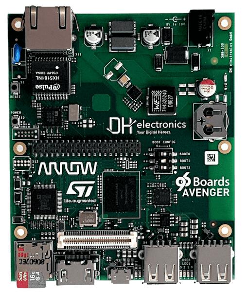
최대 209 MHz Cortex-M4F/MPU에서 실행
A7의 bootloader 또는 Linux remoteproc가 M4 image를 RAM에 적재
Linux remoteproc가 읽는 RAM console, 선택적으로 UART7 사용
Part 2
접을 수 있는 영어 원문 전체
영어 원문 전체 펼치기
DA6C46EE2BCAF286C892BEDB0534C3728CB06C5655D8E2DBC93DCD32F0D3D723
.. _96b_avenger96:

96Boards Avenger96
##################

Overview
********

96Boards Avenger96 board is based on ST Microelectronics STM32MP157A
multi-core processor, composed of a dual Cortex®-A7 and a single Cortex®-M4
core. Zephyr OS is ported to run on the Cortex®-M4 core.

- Board features:

  - PMIC: STPMIC1A
  - RAM: 1024 Mbyte @ 533MHz
  - Storage:

    - eMMC: v4.51: 8 Gbyte
    - QSPI: 2Mbyte
    - EEPROM: 128 byte
    - microSD Socket: UHS-1 v3.01
  - Ethernet: 10/100/1000 Mbit/s, IEEE 802.3 Compliant
  - Wireless:

    - WiFi: 5 GHz & 2.4GHz IEEE 802.11a/b/g/n/ac
    - Bluetooth: v4.2 (BR/EDR/BLE)
  - USB:

    - Host - 2x type A, 2.0 high-speed
    - OTG: - 1x type micro-AB, 2.0 high-speed
  - HDMI: WXGA (1366x768)@ 60 fps, HDMI 1.4
  - Connectors:

    - 40-Pin Low Speed Header
    - 60-Pin High Speed Header
  - LEDs:

    - 4x Green user LEDs
    - 1x Blue Bluetooth LED
    - 1x Yellow WiFi LED
    - 1x Red power supply LED

.. image:: ../../../../../../../boards/96boards/avenger96/doc/img/96b_avenger96.jpg
     :align: center
     :alt: 96Boards Avenger96

More information about the board can be found at the
`96Boards website`_.

Hardware
********

The STM32MP157A SoC provides the following hardware capabilities:

- Core:

  - 32-bit dual-core Arm® Cortex®-A7

    - L1 32-Kbyte I / 32-Kbyte D for each core
    - 256-Kbyte unified level 2 cache
    - Arm® NEON™

  - 32-bit Arm® Cortex®-M4 with FPU/MPU

    - Up to 209 MHz (Up to 703 CoreMark®)

- Memories:

  - External DDR memory up to 1 Gbyte.
  - 708 Kbytes of internal SRAM: 256 KB of AXI SYSRAM + 384 KB of AHB SRAM +
    64 KB of AHB SRAM in backup domain.
  - Dual mode Quad-SPI memory interface
  - Flexible external memory controller with up to 16-bit data bus

- Clock management:

  - Internal oscillators: 64 MHz HSI oscillator, 4 MHz CSI oscillator, 32 kHz
    LSI oscillator
  - External oscillators: 8-48 MHz HSE oscillator, 32.768 kHz LSE oscillator
  - 6 × PLLs with fractional mode

- General-purpose input/outputs:

  - Up to 176 I/O ports with interrupt capability

- Interconnect matrix

- 3 DMA controllers

- Communication peripherals:

  - 6 × I2C FM+ (1 Mbit/s, SMBus/PMBus)
  - 4 × UART + 4 × USART (12.5 Mbit/s, ISO7816 interface, LIN, IrDA, SPI slave)
  - 6 × SPI (50 Mbit/s, including 3 with full duplex I2S audio class accuracy)
  - 4 × SAI (stereo audio: I2S, PDM, SPDIF Tx)
  - SPDIF Rx with 4 inputs
  - HDMI-CEC interface
  - MDIO Slave interface
  - 3 × SDMMC up to 8-bit (SD / e•MMC™ / SDIO)
  - 2 × CAN controllers supporting CAN FD protocol, TTCAN capability
  - 2 × USB 2.0 high-speed Host+ 1 × USB 2.0 full-speed OTG simultaneously
  - 10/100M or Gigabit Ethernet GMAC (IEEE 1588v2 hardware, MII/RMII/GMII/RGMI)
  - 8- to 14-bit camera interface up to 140 Mbyte/s
  - 6 analog peripherals
  - 2 × ADCs with 16-bit max. resolution.
  - 1 × temperature sensor
  - 2 × 12-bit D/A converters (1 MHz)
  - 1 × digital filters for sigma delta modulator (DFSDM) with 8 channels/6
    filters
  - Internal or external ADC/DAC reference VREF+

- Graphics:

  - 3D GPU: Vivante® - OpenGL® ES 2.0
  - LCD-TFT controller, up to 24-bit // RGB888, up to WXGA (1366 × 768) @60 fps
  - MIPI® DSI 2 data lanes up to 1 GHz each

- Timers:

  - 2 × 32-bit timers with up to 4 IC/OC/PWM or pulse counter and quadrature
    (incremental) encoder input
  - 2 × 16-bit advanced motor control timers
  - 10 × 16-bit general-purpose timers (including 2 basic timers without PWM)
  - 5 × 16-bit low-power timers
  - RTC with sub-second accuracy and hardware calendar
  - 2 × 4 Cortex®-A7 system timers (secure, non-secure, virtual, hypervisor)
  - 1 × SysTick Cortex®-M4 timer

- Hardware acceleration:

  - HASH (MD5, SHA-1, SHA224, SHA256), HMAC
  - 2 × true random number generator (3 oscillators each)
  - 2 × CRC calculation unit

- Debug mode:

  - Arm® CoreSight™ trace and debug: SWD and JTAG interfaces
  - 8-Kbyte embedded trace buffer
  - 3072-bit fuses including 96-bit unique ID, up to 1184-bit available for user

More information about STM32P157A can be found here:

- `STM32MP157A on www.st.com`_
- `STM32MP157A reference manual`_

Supported Features
==================

The Zephyr 96b_avenger96 board configuration supports the following hardware
features:

+-----------+------------+-------------------------------------+
| Interface | Controller | Driver/Component                    |
+===========+============+=====================================+
| NVIC      | on-chip    | nested vector interrupt controller  |
+-----------+------------+-------------------------------------+
| GPIO      | on-chip    | gpio                                |
+-----------+------------+-------------------------------------+
| UART      | on-chip    | serial port-polling;                |
|           |            | serial port-interrupt               |
+-----------+------------+-------------------------------------+
| PINMUX    | on-chip    | pinmux                              |
+-----------+------------+-------------------------------------+

The default configuration can be found in
:zephyr_file:`boards/96boards/avenger96/96b_avenger96_defconfig`


Connections and IOs
===================

96Boards Avenger96 Board schematic is available here:
`Avenger96 board schematics`_.


Default Zephyr Peripheral Mapping:
----------------------------------

- UART_7 TX/RX/RTS/CTS : PE8/PE7/PE9/PE10 (UART console)
- UART_4 TX/RX : PD1/PB2

System Clock
------------

The Cortex®-M4 Core is configured to run at a 209 MHz clock speed. This value
must match the configured mlhclk_ck frequency.

Serial Port
-----------

96Boards Avenger96 board has 3 U(S)ARTs. The Zephyr console output is assigned
by default to the RAM console to be dumped by the Linux Remoteproc Framework
on Cortex®-A7 core. Alternatively, Zephyr console output can be assigned to
UART7 which is disabled by default. UART console can be enabled through
board's devicetree and 96b_avenger96_defconfig board file (or prj.conf
project files), and will disable existing RAM console output. Default UART
console settings are 115200 8N1.

Programming and Debugging
*************************

The STM32MP157A doesn't have QSPI flash for the Cortex®-M4  and it needs to be
started by the Cortex®-A7 core. The Cortex®-A7 core is responsible to load the
Cortex®-M4 binary application into the RAM, and get the Cortex®-M4 out of reset.
The Cortex®-A7 can perform these steps at bootloader level or after the Linux
system has booted.

The Cortex®-M4 can use up to 2 different RAMs. The program pointer starts at
address 0x00000000 (RETRAM), the vector table should be loaded at this address
These are the memory mappings for Cortex®-A7 and Cortex®-M4:

+------------+-----------------------+------------------------+----------------+
| Region     | Cortex®-A7            | Cortex®-M4             | Size           |
+============+=======================+========================+================+
| RETRAM     | 0x38000000-0x3800FFFF | 0x00000000-0x0000FFFF  | 64KB           |
+------------+-----------------------+------------------------+----------------+
| MCUSRAM    | 0x10000000-0x1005FFFF | 0x10000000-0x1005FFFF  | 384KB          |
+------------+-----------------------+------------------------+----------------+
| DDR        | 0xC0000000-0xFFFFFFFF |                        | up to 1 GB     |
+------------+-----------------------+------------------------+----------------+


Refer to `stm32mp157 boot Cortex-M4 firmware`_ wiki page for instruction
to load and start the Cortex-M4 firmware.

Debugging
=========

You can debug an application using OpenOCD and GDB. The Solution proposed below
is based on the Linux STM32MP1 SDK OpenOCD and is available only for a Linux
environment. The firmware must first be loaded by the Cortex®-A7. Developer
then attaches the debugger to the running Zephyr using OpenOCD.

Prerequisite
------------
install `stm32mp1 developer package`_.

1) start OpenOCD in a dedicated terminal

   - Start up the  sdk environment::

      source <SDK installation directory>/environment-setup-cortexa7hf-neon-vfpv4-openstlinux_weston-linux-gnueabi

   - Start OpenOCD::

      ${OECORE_NATIVE_SYSROOT}/usr/bin/openocd -s ${OECORE_NATIVE_SYSROOT}/usr/share/openocd/scripts -f board/stm32mp15x_ev1_jlink_jtag.cfg

2) run gdb in Zephyr environment

   .. code-block:: console

      # On Linux
      cd $ZEPHYR_BASE/samples/hello_world
      mkdir -p build && cd build

      # Use cmake to configure a Ninja-based build system:
      cmake -GNinja -DBOARD=96b_avenger96 ..

      # Now run ninja on the generated build system:
      ninja debug

.. _96Boards website:
   https://www.96boards.org/product/avenger96/

.. _STM32MP157A on www.st.com:
   https://www.st.com/content/st_com/en/products/microcontrollers-microprocessors/stm32-arm-cortex-mpus/stm32mp1-series/stm32mp157/stm32mp157a.html

.. _STM32MP157A reference manual:
   https://www.st.com/resource/en/reference_manual/DM00327659.pdf

.. _Avenger96 board schematics:
   https://www.96boards.org/documentation/consumer/avenger96/hardware-docs/files/avenger96-schematics.pdf

.. _stm32mp1 developer package:
   https://wiki.st.com/stm32mpu/index.php/STM32MP1_Developer_Package#Installing_the_SDK

.. _stm32mp157 boot Cortex-M4 firmware:
   https://wiki.st.com/stm32mpu/index.php/Linux_remoteproc_framework_overview#How_to_use_the_framework
Part 3
한국어 전문 번역
개요
96Boards Avenger96은 dual Cortex-A7과 single Cortex-M4 core로 구성된 STMicroelectronics STM32MP157A multicore processor 기반입니다. Zephyr OS는 Cortex-M4 core에서 실행되도록 port됐습니다.
보드 기능
- PMIC: STPMIC1A
- RAM: 533 MHz 1,024 MB
- 저장장치: eMMC v4.51 8 GB, QSPI 2 MB, EEPROM 128 byte, UHS-1 v3.01 microSD socket
- Ethernet: IEEE 802.3 compliant 10/100/1000 Mbit/s
- 무선: 5/2.4 GHz IEEE 802.11a/b/g/n/ac Wi-Fi, Bluetooth v4.2 BR/EDR/BLE
- USB: type-A USB 2.0 high-speed host 2개, micro-AB USB 2.0 high-speed OTG 1개
- HDMI 1.4: WXGA 1366×768 @ 60 fps
- connector: 40-pin Low Speed Header, 60-pin High Speed Header
- LED: green user LED 4개, blue Bluetooth LED 1개, yellow Wi-Fi LED 1개, red power LED 1개
보드의 자세한 정보는 96Boards website에서 확인할 수 있습니다.
하드웨어
STM32MP157A SoC는 다음 하드웨어 기능을 제공합니다.
Core
- 32-bit dual-core Arm Cortex-A7
- core별 L1 instruction 32 KB와 data 32 KB
- unified L2 cache 256 KB
- Arm NEON
- FPU/MPU를 갖춘 32-bit Arm Cortex-M4, 최대 209 MHz와 최대 703 CoreMark
Memory
- 최대 1 GB external DDR
- internal SRAM 708 KB: AXI SYSRAM 256 KB + AHB SRAM 384 KB + backup domain AHB SRAM 64 KB
- dual-mode Quad-SPI memory interface
- 최대 16-bit data bus의 flexible external memory controller
Clock management
- internal oscillator: HSI 64 MHz, CSI 4 MHz, LSI 32 kHz
- external oscillator: HSE 8~48 MHz, LSE 32.768 kHz
- fractional mode PLL 6개
GPIO와 interconnect
- interrupt 가능한 I/O port 최대 176개
- interconnect matrix
- DMA controller 3개
통신·analog peripheral
- I2C FM+ 6개: 1 Mbit/s, SMBus/PMBus
- UART 4개 + USART 4개: 12.5 Mbit/s, ISO7816, LIN, IrDA, SPI slave
- SPI 6개: 50 Mbit/s, 그중 3개는 full-duplex I2S audio-class accuracy 지원
- SAI 4개: stereo I2S, PDM, SPDIF Tx
- input 4개의 SPDIF Rx
- HDMI-CEC
- MDIO slave
- 최대 8-bit SDMMC 3개: SD/eMMC/SDIO
- CAN FD와 TTCAN을 지원하는 CAN controller 2개
- USB 2.0 high-speed host 2개와 USB 2.0 full-speed OTG 1개를 동시 사용
- IEEE 1588v2 hardware를 갖춘 10/100M 또는 Gigabit Ethernet GMAC, MII/RMII/GMII/RGMII
- 최대 140 MB/s, 8~14-bit camera interface
- analog peripheral 6개, 최대 16-bit ADC 2개, temperature sensor 1개, 1 MHz 12-bit DAC 2개
- 8 channel/6 filter sigma-delta modulator용 DFSDM 1개
- internal/external ADC/DAC reference
VREF+
Graphics
- Vivante 3D GPU, OpenGL ES 2.0
- 최대 24-bit RGB888와 WXGA 1366×768 @ 60 fps LCD-TFT controller
- lane당 최대 1 GHz인 MIPI DSI data lane 2개
Timer
- IC/OC/PWM 또는 pulse counter와 quadrature encoder input을 최대 4개 제공하는 32-bit timer 2개
- 16-bit advanced motor-control timer 2개
- PWM 없는 basic timer 2개를 포함한 16-bit general-purpose timer 10개
- 16-bit low-power timer 5개
- sub-second accuracy와 hardware calendar를 갖춘 RTC
- Cortex-A7용 secure/non-secure/virtual/hypervisor system timer 2×4개
- Cortex-M4 SysTick timer 1개
Hardware acceleration과 debug
- MD5, SHA-1, SHA224, SHA256 HASH와 HMAC
- 각각 oscillator 3개인 true random-number generator 2개
- CRC unit 2개
- SWD/JTAG를 제공하는 Arm CoreSight trace/debug
- embedded trace buffer 8 KB
- 96-bit unique ID와 사용자용 최대 1,184-bit를 포함한 fuse 3,072-bit
자세한 내용은 STM32MP157A product page와 reference manual을 참고합니다.
지원 기능
| Interface | Controller | Driver/Component |
|---|---|---|
| NVIC | on-chip | nested vector interrupt controller |
| GPIO | on-chip | gpio |
| UART | on-chip | serial port-polling; serial port-interrupt |
| PINMUX | on-chip | pinmux |
기본 설정 파일은 boards/96boards/avenger96/96b_avenger96_defconfig입니다.
연결과 I/O
보드 회로도는 Avenger96 board schematics에서 확인할 수 있습니다.
기본 Zephyr peripheral mapping
UART_7 TX/RX/RTS/CTS: PE8/PE7/PE9/PE10, UART consoleUART_4 TX/RX: PD1/PB2
System clock
Cortex-M4 core는 209 MHz로 동작하도록 설정됩니다. 이 값은 설정된 mlhclk_ck 주파수와 일치해야 합니다.
Serial port
Avenger96에는 U(S)ART가 3개 있습니다. Zephyr console은 기본적으로 RAM console에 할당되며 Cortex-A7의 Linux Remoteproc Framework가 이를 dump합니다. 대신 기본적으로 disabled인 UART7에 console을 할당할 수 있습니다. board devicetree와 96b_avenger96_defconfig 또는 project prj.conf에서 UART console을 활성화하면 기존 RAM console은 비활성화됩니다. 기본 UART 설정은 115200 8N1입니다.
프로그래밍과 디버깅
STM32MP157A에는 Cortex-M4용 QSPI flash가 없으며 Cortex-A7이 M4를 시작해야 합니다. A7은 Cortex-M4 binary를 RAM에 적재하고 M4의 reset을 해제합니다. 이 작업은 bootloader 단계 또는 Linux boot 후에 수행할 수 있습니다.
Cortex-M4는 최대 두 종류의 RAM을 사용할 수 있습니다. program pointer는 0x00000000의 RETRAM에서 시작하므로 vector table을 이 주소에 적재해야 합니다. A7과 M4의 memory mapping은 다음과 같습니다.
| Region | Cortex-A7 | Cortex-M4 | Size |
|---|---|---|---|
| RETRAM | 0x38000000-0x3800FFFF | 0x00000000-0x0000FFFF | 64 KB |
| MCUSRAM | 0x10000000-0x1005FFFF | 0x10000000-0x1005FFFF | 384 KB |
| DDR | 0xC0000000-0xFFFFFFFF | 최대 1 GB |
Cortex-M4 firmware의 load와 start 방법은 stm32mp157 boot Cortex-M4 firmware wiki를 참고합니다.
Debugging
OpenOCD와 GDB로 애플리케이션을 debug할 수 있습니다. 아래 방법은 Linux STM32MP1 SDK OpenOCD 기반이며 Linux 환경에서만 사용할 수 있습니다. 먼저 A7이 firmware를 적재해야 하며, 그 뒤 developer가 OpenOCD로 실행 중인 Zephyr에 debugger를 attach합니다.
사전 조건
stm32mp1 developer package를 설치합니다.
전용 terminal에서 OpenOCD를 시작합니다.
source <SDK installation directory>/environment-setup-cortexa7hf-neon-vfpv4-openstlinux_weston-linux-gnueabi
${OECORE_NATIVE_SYSROOT}/usr/bin/openocd -s ${OECORE_NATIVE_SYSROOT}/usr/share/openocd/scripts -f board/stm32mp15x_ev1_jlink_jtag.cfg
Zephyr 환경에서 GDB를 실행합니다.
# Linux에서
cd $ZEPHYR_BASE/samples/hello_world
mkdir -p build && cd build

# Ninja build system 생성
cmake -GNinja -DBOARD=96b_avenger96 ..

# 생성된 build system에서 debug
ninja debug
참고 자료
- 96Boards Avenger96
- STM32MP157A product page
- STM32MP157A reference manual
- Avenger96 schematics
- STM32MP1 Developer Package
- Linux remoteproc framework overview
Source
출처
영어 원문에는 문단, 문서 지시문, 표, 코드, 코드 심벌, 경로를 그대로 보존했습니다.