Part 1
요약·해설
Aerocore 2는 96Boards CE board 위에 얹는 drone용 mezzanine이지만 STM32F427VIT6 독립 보드로도 사용할 수 있습니다. 비행 제어에 필요한 PWM 8채널, GPS, Spektrum receiver, CAN, ADC, I2C, SPI를 별도 connector에 배치한 것이 핵심입니다.
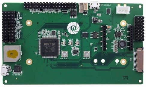
168 MHz STM32F427VIT6 Cortex-M4F, flash 2 MB, SRAM 256 KB
PWM 8채널, GPS UART, Spektrum UART, CAN, ADC·I2C·SPI
USART7, 115200 8N1, 외부 USB-TTL dongle 필요
Part 2
접을 수 있는 영어 원문 전체
영어 원문 전체 펼치기
415279561C961085552DB18FADEB620B1703F173385116CFFCC55EDB11B6C7CE
.. _96b_aerocore2_board:

96Boards Aerocore2
##################

Overview
********

The 96Boards Aerocore2 Mezzanine is based on the STMicroelectronics
STM32F427VIT6 Cortex-M4 CPU primarily designed for use in drones.
This board acts as a mezzanine platform for all 96Boards CE compliant
boards. It can also be used as a standalone board.


.. figure:: ../../../../../../../boards/96boards/aerocore2/doc/img/96b_aerocore2.jpg
     :align: center
     :alt: 96Boards Aerocore2

     96Boards Aerocore2

Hardware
********

96Boards Aerocore2 provides the following hardware components:

- STM32F427VIT6 in LQFP100 package
- ARM |reg| 32-bit Cortex |reg|-M4 CPU with FPU
- 168 MHz max CPU frequency
- VDD from 1.7 V to 3.6 V
- 2048 KB Flash
- 256 KB SRAM
- GPIO with external interrupt capability
- 12-bit ADC with 16 channels
- RTC
- Advanced-control Timers (2)
- General Purpose Timers (10)
- Watchdog Timers (2)
- USART/UART (4)
- I2C (3)
- SPI (3)
- SDIO
- USB 2.0 OTG FS
- DMA Controller

More information about STM32F427VIT6 can be found here:
       - `STM32F427 on www.st.com`_

Supported Features
==================

The Zephyr 96b_aerocore2 board configuration supports the following hardware
features:

+------------+------------+-------------------------------------+
| Interface  | Controller | Driver/Component                    |
+============+============+=====================================+
| NVIC       | on-chip    | nested vector interrupt controller  |
+------------+------------+-------------------------------------+
| SYSTICK    | on-chip    | system clock                        |
+------------+------------+-------------------------------------+
| UART       | on-chip    | serial port                         |
+------------+------------+-------------------------------------+
| GPIO       | on-chip    | gpio                                |
+------------+------------+-------------------------------------+
| PINMUX     | on-chip    | pinmux                              |
+------------+------------+-------------------------------------+
| FLASH      | on-chip    | flash                               |
+------------+------------+-------------------------------------+
| SPI        | on-chip    | spi                                 |
+------------+------------+-------------------------------------+
| I2C        | on-chip    | i2c                                 |
+------------+------------+-------------------------------------+
| PWM        | on-chip    | timers / pwm                        |
+------------+------------+-------------------------------------+
| USB OTG FS | on-chip    | USB device                          |
+------------+------------+-------------------------------------+
| ADC        | on-chip    | adc                                 |
+------------+------------+-------------------------------------+

More details about the board can be found at `96Boards website`_.

The default configuration can be found in
:zephyr_file:`boards/96boards/aerocore2/96b_aerocore2_defconfig`

Connections and IOs
===================

LED
---

- LED1 / User1 LED = PE10
- LED2 / User2 LED = PE9

External Connectors
-------------------

Octal PWM Header (J1)

+-------+-------------+-------------------------+-------+-------------+-------+-------------+
| PIN # | Signal Name | STM32F427 Functions Pin | PIN # | Signal Name | Pin # | Signal Name |
+=======+=============+=========================+=======+=============+=======+=============+
| 1     | PWM4_CH1    | PD12                    | 2     | 5.0v        | 3     | GND         |
+-------+-------------+-------------------------+-------+-------------+-------+-------------+
| 4     | PWM4_CH2    | PD13                    | 5     | 5.0v        | 6     | GND         |
+-------+-------------+-------------------------+-------+-------------+-------+-------------+
| 7     | PWM4_CH3    | PD14                    | 8     | 5.0v        | 9     | GND         |
+-------+-------------+-------------------------+-------+-------------+-------+-------------+
| 10    | PWM4_CH4    | PD15                    | 11    | 5.0v        | 12    | GND         |
+-------+-------------+-------------------------+-------+-------------+-------+-------------+
| 13    | PWM5_CH1    | PA0                     | 14    | 5.0v        | 15    | GND         |
+-------+-------------+-------------------------+-------+-------------+-------+-------------+
| 16    | PWM5_CH2    | PA1                     | 17    | 5.0v        | 18    | GND         |
+-------+-------------+-------------------------+-------+-------------+-------+-------------+
| 19    | PWM5_CH3    | PA2                     | 20    | 5.0v        | 21    | GND         |
+-------+-------------+-------------------------+-------+-------------+-------+-------------+
| 22    | PWM5_CH4    | PA3                     | 23    | 5.0v        | 24    | GND         |
+-------+-------------+-------------------------+-------+-------------+-------+-------------+


IO Header J11

+-------+-------------+-------+-------------+
| PIN # | Signal Name | PIN # | Signal Name |
+=======+=============+=======+=============+
| 1     | PB9         | 2     | PB8*        |
+-------+-------------+-------+-------------+
| 3     | PC9         | 4     | PB0         |
+-------+-------------+-------+-------------+
| 5     | PE5         | 6     | NA          |
+-------+-------------+-------+-------------+
| 7     | PE6         | 8     | NA          |
+-------+-------------+-------+-------------+
| 9     | PC6         | 10    | NA          |
+-------+-------------+-------+-------------+
| 11    | PC7         | 12    | NA          |
+-------+-------------+-------+-------------+
| 13    | PC8         | 14    | NA          |
+-------+-------------+-------+-------------+
| 15    | PA8         | 16    | GND         |
+-------+-------------+-------+-------------+
| 17    | PA9         | 18    | 3v3         |
+-------+-------------+-------+-------------+
| 19    | PA10        | 20    | GND         |
+-------+-------------+-------+-------------+

* PB8 is connected to a watchdog buzzer, It needs to be pulsed every 10 seconds to keep the buzzer silent.

IO Header J5

+-------+-------------+-------------------------+-------+-------------+-------------------------+
| PIN # | Signal Name | STM32F427 Functions Pin | PIN # | Signal Name | STM32F427 Functions Pin |
+=======+=============+=========================+=======+=============+=========================+
| 1     | AGND        | AGND                    | 2     | ADC1_13     | PC3                     |
+-------+-------------+-------------------------+-------+-------------+-------------------------+
| 3     | ADC1_12     | PC2                     | 4     | ADC1_11     | PC1                     |
+-------+-------------+-------------------------+-------+-------------+-------------------------+
| 5     | I2C_SDA     | PB11                    | 6     | GND         | GND                     |
+-------+-------------+-------------------------+-------+-------------+-------------------------+
| 7     | I2C_SCL     | PB10                    | 8     | VCC 3v3     | VCC 3v3                 |
+-------+-------------+-------------------------+-------+-------------+-------------------------+
| 9     | NC          | NC                      | 10    | NC          | NC                      |
+-------+-------------+-------------------------+-------+-------------+-------------------------+
| 11    | NC          | NC                      | 12    | NC          | NC                      |
+-------+-------------+-------------------------+-------+-------------+-------------------------+
| 13    | UART_TX 7   | PE8                     | 14    | GND         | GND                     |
+-------+-------------+-------------------------+-------+-------------+-------------------------+
| 15    | UART_RX 7   | PE7                     | 16    | GND         | GND                     |
+-------+-------------+-------------------------+-------+-------------+-------------------------+
| 17    | UART_TX 2   | PD5                     | 18    | GND         | GND                     |
+-------+-------------+-------------------------+-------+-------------+-------------------------+
| 19    | UART_TX 2   | PD6                     | 20    | GND         | GND                     |
+-------+-------------+-------------------------+-------+-------------+-------------------------+
| 21    | NC          | NC                      | 10    | NC          | NC                      |
+-------+-------------+-------------------------+-------+-------------+-------------------------+
| 23    | NC          | NC                      | 10    | NC          | NC                      |
+-------+-------------+-------------------------+-------+-------------+-------------------------+
| 25    | SPI1_NIRQ   | PC5                     | 26    | GND         | GND                     |
+-------+-------------+-------------------------+-------+-------------+-------------------------+
| 27    | SPI1_CLK    | PA5                     | 28    | SPI1_MISO   | PA6                     |
+-------+-------------+-------------------------+-------+-------------+-------------------------+
| 29    | SPI1_CS0    | PA4                     | 30    | SPI1_MOSI   | PA7                     |
+-------+-------------+-------------------------+-------+-------------+-------------------------+
| 31    | CAN_TX      | PD1                     | 32    | CANH        | NC                      |
+-------+-------------+-------------------------+-------+-------------+-------------------------+
| 33    | CAN_RX      | PD0                     | 34    | CANL        | NC                      |
+-------+-------------+-------------------------+-------+-------------+-------------------------+


GPS connector J15

+-------+-------------+-------------------------+
| PIN # | Signal Name | STM32F427 Functions Pin |
+=======+=============+=========================+
| 1     | V_OUT 5v    | NC                      |
+-------+-------------+-------------------------+
| 2     | UART1_TX    | PB6                     |
+-------+-------------+-------------------------+
| 3     | UART1_RX    | PB7                     |
+-------+-------------+-------------------------+
| 4     | VCC 3v3     | NC                      |
+-------+-------------+-------------------------+
| 5     | GND         | GND                     |
+-------+-------------+-------------------------+


Spektrum connector J3

+-------+-------------+-------------------------+
| PIN # | Signal Name | STM32F427 Functions Pin |
+=======+=============+=========================+
| 1     | VCC 3v3     | NC                      |
+-------+-------------+-------------------------+
| 2     | GND         | GND                     |
+-------+-------------+-------------------------+
| 3     | UART8_RX    | PE0                     |
+-------+-------------+-------------------------+


External Clock Sources
----------------------

STM32F4 has one external oscillator. The frequency of the clock is
32.768 kHz. The internal 16MHz clock is used as the main clock.

Serial Port
-----------

96Boards Aerocore2 board has up to 4 U(S)ARTs. The Zephyr console output is
assigned to USART7. Default settings are 115200 8N1.

I2C
---

96Boards Aerocore2 board has 1 I2C port. The default I2C mapping for Zephyr is:

- I2C1_SCL : PB10
- I2C1_SDA : PB11

SPI
---

96Boards Aerocore2 board has 1 SPI port. The default SPI mapping for Zephyr is:

- SPI1_CS0  : PA4
- SPI1_SCK  : PA5
- SPI1_MISO : PA6
- SPI1_MOSI : PA7

USB
===

96Boards Aerocore2 board has a USB OTG dual-role device (DRD) controller that
supports both device and host functions through its mini "OTG" USB connector.
Only USB device functions are supported in Zephyr at the moment.

Programming and Debugging
*************************

There are 2 main entry points for flashing STM32F4X SoCs, one using the ROM
bootloader, and another by using the SWD debug port (which requires additional
hardware). Flashing using the ROM bootloader requires a special activation
pattern, which can be triggered by using the BOOT0 pin. The ROM bootloader
supports flashing via USB (DFU), UART, I2C and SPI. You can read more about
how to enable and use the ROM bootloader by checking the application
note `AN2606`_, page 109.

Flashing
========

Installing dfu-util
-------------------

It is recommended to use at least v0.8 of `dfu-util`_. The package available in
debian/ubuntu can be quite old, so you might have to build dfu-util from source.

Flashing an Application to 96Boards Aerocore2
---------------------------------------------

Connect the micro-USB cable to the USB OTG/STM_CONSOLE Aerocore2 port and to your computer.
The board should power ON. Force the board into DFU mode by keeping the BOOT0
switch pressed while pressing and releasing the RST switch.

The BOOT button is located at the back-side of the PCB.

Confirm that the board is in DFU mode:

.. code-block:: console

   $ sudo dfu-util -l
   dfu-util 0.8
   Copyright 2005-2009 Weston Schmidt, Harald Welte and OpenMoko Inc.
   Copyright 2010-2014 Tormod Volden and Stefan Schmidt
   This program is Free Software and has ABSOLUTELY NO WARRANTY
   Please report bugs to [email protected]
   Found DFU: [0483:df11] ver=2200, devnum=15, cfg=1, intf=0, alt=3, name="@Device Feature/0xFFFF0000/01*004 e", serial="3574364C3034"
   Found DFU: [0483:df11] ver=2200, devnum=15, cfg=1, intf=0, alt=2, name="@OTP Memory /0x1FFF7800/01*512 e,01*016 e", serial="3574364C3034"
   Found DFU: [0483:df11] ver=2200, devnum=15, cfg=1, intf=0, alt=1, name="@Option Bytes /0x1FFFC000/01*016 e", serial="3574364C3034"
   Found DFU: [0483:df11] ver=2200, devnum=15, cfg=1, intf=0, alt=0, name="@Internal Flash /0x08000000/04*016Kg,01*064Kg,03*128Kg", serial="3574364C3034"
   Found Runtime: [05ac:8290] ver=0104, devnum=2, cfg=1, intf=5, alt=0, name="UNKNOWN", serial="UNKNOWN"

You should see following confirmation on your Linux host:

.. code-block:: console

   $ dmesg
   usb 1-2.1: new full-speed USB device number 14 using xhci_hcd
   usb 1-2.1: New USB device found, idVendor=0483, idProduct=df11
   usb 1-2.1: New USB device strings: Mfr=1, Product=2, SerialNumber=3
   usb 1-2.1: Product: STM32 BOOTLOADER
   usb 1-2.1: Manufacturer: STMicroelectronics
   usb 1-2.1: SerialNumber: 3574364C3034

Then build and flash an application. Here is an example for the
:ref:`hello_world` application.

.. zephyr-app-commands::
   :zephyr-app: samples/hello_world
   :board: 96b_aerocore2
   :goals: build flash

Connect a USB-TTL dongle to the UART_7 header port and to your computer.
Run your favorite terminal program to listen for output.

.. code-block:: console

   $ minicom -D <tty_device> -b 115200

Replace :code:`<tty_device>` with the port where the board 96Boards Aerocore2
can be found. For example, under Linux, :code:`/dev/ttyUSB0`.
The ``-b`` option sets baud rate ignoring the value from config.

Press the Reset button and you should see the following message in your
terminal:

.. code-block:: console

   Hello World! arm

.. _96Boards website:
   https://www.96boards.org/product/aerocore2/

.. _STM32F427 on www.st.com:
   https://www.st.com/en/microcontrollers-microprocessors/stm32f427vi.html

.. _dfu-util:
   http://dfu-util.sourceforge.net/build.html

.. _AN2606:
   https://www.st.com/content/ccc/resource/technical/document/application_note/b9/9b/16/3a/12/1e/40/0c/CD00167594.pdf/files/CD00167594.pdf/jcr:content/translations/en.CD00167594.pdf
Part 3
한국어 전문 번역
개요
96Boards Aerocore 2 Mezzanine은 주로 drone에 사용하도록 설계된 STMicroelectronics STM32F427VIT6 Cortex-M4 CPU 기반입니다. 모든 96Boards CE compliant board의 mezzanine platform으로 동작하며 독립형 board로도 사용할 수 있습니다.
하드웨어
Aerocore 2는 다음 하드웨어 구성요소를 제공합니다.
- LQFP100 package의 STM32F427VIT6
- FPU를 갖춘 Arm 32-bit Cortex-M4 CPU
- 최대 CPU 주파수 168 MHz
- VDD 1.7~3.6 V
- flash 2,048 KB, SRAM 256 KB
- 외부 interrupt 가능한 GPIO
- 16-channel 12-bit ADC
- RTC
- advanced-control timer 2개, general-purpose timer 10개, watchdog timer 2개
- USART/UART 4개, I2C 3개, SPI 3개
- SDIO, USB 2.0 OTG FS, DMA controller
STM32F427VIT6의 자세한 정보는 STMicroelectronics product page를 참고합니다.
지원 기능
Zephyr의 96b_aerocore2 board 설정은 다음 기능을 지원합니다.
| Interface | Controller | Driver/Component |
|---|---|---|
| NVIC | on-chip | nested vector interrupt controller |
| SYSTICK | on-chip | system clock |
| UART | on-chip | serial port |
| GPIO | on-chip | gpio |
| PINMUX | on-chip | pinmux |
| FLASH | on-chip | flash |
| SPI | on-chip | spi |
| I2C | on-chip | i2c |
| PWM | on-chip | timers / pwm |
| USB OTG FS | on-chip | USB device |
| ADC | on-chip | adc |
기본 설정은 boards/96boards/aerocore2/96b_aerocore2_defconfig에서 확인할 수 있습니다.
연결과 I/O
LED
LED1 / User1 LED = PE10LED2 / User2 LED = PE9
외부 connector
Octal PWM Header (J1)
| PIN # | Signal Name | STM32F427 Functions Pin | PIN # | Signal Name | PIN # | Signal Name |
|---|---|---|---|---|---|---|
| 1 | PWM4_CH1 | PD12 | 2 | 5.0v | 3 | GND |
| 4 | PWM4_CH2 | PD13 | 5 | 5.0v | 6 | GND |
| 7 | PWM4_CH3 | PD14 | 8 | 5.0v | 9 | GND |
| 10 | PWM4_CH4 | PD15 | 11 | 5.0v | 12 | GND |
| 13 | PWM5_CH1 | PA0 | 14 | 5.0v | 15 | GND |
| 16 | PWM5_CH2 | PA1 | 17 | 5.0v | 18 | GND |
| 19 | PWM5_CH3 | PA2 | 20 | 5.0v | 21 | GND |
| 22 | PWM5_CH4 | PA3 | 23 | 5.0v | 24 | GND |
IO Header J11
| PIN # | Signal Name | PIN # | Signal Name |
|---|---|---|---|
| 1 | PB9 | 2 | PB8* |
| 3 | PC9 | 4 | PB0 |
| 5 | PE5 | 6 | NA |
| 7 | PE6 | 8 | NA |
| 9 | PC6 | 10 | NA |
| 11 | PC7 | 12 | NA |
| 13 | PC8 | 14 | NA |
| 15 | PA8 | 16 | GND |
| 17 | PA9 | 18 | 3v3 |
| 19 | PA10 | 20 | GND |
* PB8: watchdog buzzer에 연결돼 있습니다. buzzer를 조용히 유지하려면 10초마다 pulse를 인가해야 합니다.
IO Header J5
| PIN # | Signal Name | STM32F427 Functions Pin | PIN # | Signal Name | STM32F427 Functions Pin |
|---|---|---|---|---|---|
| 1 | AGND | AGND | 2 | ADC1_13 | PC3 |
| 3 | ADC1_12 | PC2 | 4 | ADC1_11 | PC1 |
| 5 | I2C_SDA | PB11 | 6 | GND | GND |
| 7 | I2C_SCL | PB10 | 8 | VCC 3v3 | VCC 3v3 |
| 9 | NC | NC | 10 | NC | NC |
| 11 | NC | NC | 12 | NC | NC |
| 13 | UART_TX 7 | PE8 | 14 | GND | GND |
| 15 | UART_RX 7 | PE7 | 16 | GND | GND |
| 17 | UART_TX 2 | PD5 | 18 | GND | GND |
| 19 | UART_TX 2 | PD6 | 20 | GND | GND |
| 21 | NC | NC | 10 | NC | NC |
| 23 | NC | NC | 10 | NC | NC |
| 25 | SPI1_NIRQ | PC5 | 26 | GND | GND |
| 27 | SPI1_CLK | PA5 | 28 | SPI1_MISO | PA6 |
| 29 | SPI1_CS0 | PA4 | 30 | SPI1_MOSI | PA7 |
| 31 | CAN_TX | PD1 | 32 | CANH | NC |
| 33 | CAN_RX | PD0 | 34 | CANL | NC |
원문의 J5 표에는 오른쪽 열의 pin 번호 10이 두 행에서 반복됩니다. 이 번역은 원문 값을 수정하지 않고 그대로 보존했습니다.
GPS connector J15
| PIN # | Signal Name | STM32F427 Functions Pin |
|---|---|---|
| 1 | V_OUT 5v | NC |
| 2 | UART1_TX | PB6 |
| 3 | UART1_RX | PB7 |
| 4 | VCC 3v3 | NC |
| 5 | GND | GND |
Spektrum connector J3
| PIN # | Signal Name | STM32F427 Functions Pin |
|---|---|---|
| 1 | VCC 3v3 | NC |
| 2 | GND | GND |
| 3 | UART8_RX | PE0 |
외부 clock source
STM32F4에는 외부 oscillator가 하나 있으며 주파수는 32.768 kHz입니다. main clock에는 internal 16 MHz clock을 사용합니다.
Serial port
Aerocore 2에는 최대 4개의 U(S)ART가 있습니다. Zephyr console output은 USART7에 할당되며 기본 설정은 115200 8N1입니다.
I2C
보드에는 I2C port 하나가 있습니다. Zephyr 기본 mapping은 I2C1_SCL: PB10, I2C1_SDA: PB11입니다.
SPI
보드에는 SPI port 하나가 있습니다. Zephyr 기본 mapping은 SPI1_CS0: PA4, SPI1_SCK: PA5, SPI1_MISO: PA6, SPI1_MOSI: PA7입니다.
USB
Aerocore 2에는 mini “OTG” USB connector를 통해 device와 host 기능을 모두 제공하는 USB OTG dual-role device(DRD) controller가 있습니다. 현재 Zephyr에서는 USB device 기능만 지원합니다.
프로그래밍과 디버깅
STM32F4X SoC를 flash하는 주요 진입점은 ROM bootloader와 SWD debug port 두 가지입니다. SWD 방식에는 추가 하드웨어가 필요합니다. ROM bootloader 방식은 BOOT0 pin으로 특별한 활성화 pattern을 입력해야 하며 USB DFU, UART, I2C, SPI flashing을 지원합니다. 활성화 방법은 ST application note AN2606 109쪽을 참고합니다.
dfu-util 설치
dfu-util v0.8 이상을 권장합니다. Debian/Ubuntu package가 오래된 버전일 수 있으므로 source에서 직접 build해야 할 수도 있습니다.
Aerocore 2에 application flash
micro-USB cable로 Aerocore 2의 USB OTG/STM_CONSOLE port와 computer를 연결합니다. 전원이 켜지면 PCB 뒷면의 BOOT0 switch를 누른 채 RST switch를 눌렀다 놓아 DFU mode로 진입합니다.
다음 명령으로 DFU mode를 확인합니다.
$ sudo dfu-util -l
dfu-util 0.8
Copyright 2005-2009 Weston Schmidt, Harald Welte and OpenMoko Inc.
Copyright 2010-2014 Tormod Volden and Stefan Schmidt
This program is Free Software and has ABSOLUTELY NO WARRANTY
Please report bugs to [email protected]
Found DFU: [0483:df11] ver=2200, devnum=15, cfg=1, intf=0, alt=3, name="@Device Feature/0xFFFF0000/01*004 e", serial="3574364C3034"
Found DFU: [0483:df11] ver=2200, devnum=15, cfg=1, intf=0, alt=2, name="@OTP Memory /0x1FFF7800/01*512 e,01*016 e", serial="3574364C3034"
Found DFU: [0483:df11] ver=2200, devnum=15, cfg=1, intf=0, alt=1, name="@Option Bytes /0x1FFFC000/01*016 e", serial="3574364C3034"
Found DFU: [0483:df11] ver=2200, devnum=15, cfg=1, intf=0, alt=0, name="@Internal Flash /0x08000000/04*016Kg,01*064Kg,03*128Kg", serial="3574364C3034"
Found Runtime: [05ac:8290] ver=0104, devnum=2, cfg=1, intf=5, alt=0, name="UNKNOWN", serial="UNKNOWN"
Linux host에서는 다음과 같은 확인 메시지가 보여야 합니다.
$ dmesg
usb 1-2.1: new full-speed USB device number 14 using xhci_hcd
usb 1-2.1: New USB device found, idVendor=0483, idProduct=df11
usb 1-2.1: New USB device strings: Mfr=1, Product=2, SerialNumber=3
usb 1-2.1: Product: STM32 BOOTLOADER
usb 1-2.1: Manufacturer: STMicroelectronics
usb 1-2.1: SerialNumber: 3574364C3034
hello_world 예제를 build하고 flash합니다.
# Zephyr 저장소 루트에서
west build -b 96b_aerocore2 samples/hello_world
west flash
USB-TTL dongle을 UART_7 header와 computer에 연결하고 terminal program을 실행합니다.
$ minicom -D <tty_device> -b 115200<tty_device>를 Aerocore 2가 연결된 port로 바꿉니다. Linux에서는 예를 들어 /dev/ttyUSB0입니다. -b option은 설정값을 무시하고 baud rate를 지정합니다. Reset button을 누르면 다음 메시지가 보여야 합니다.
Hello World! arm참고 자료
Source
출처
영어 원문에는 문단, 문서 지시문, 표, 코드, 코드 심벌, 경로를 그대로 보존했습니다.